Eureka AIR delivers breakthrough ideas for toughest innovation challenges, trusted by R&D personnel around the world.

Rolling rope line winding method

A rope and rolling technology, which is applied in the field of physics teaching instruments, can solve the problems of different lengths of the left and right ropes, the tilt of the rotating shaft, and the impact on the progress, so as to achieve the effect of improving the experimental effect

Inactive Publication Date: 2011-12-14
张静文
View PDF0 Cites 2 Cited by
  • Summary
  • Abstract
  • Description
  • Claims
  • Application Information

AI Technical Summary

Problems solved by technology

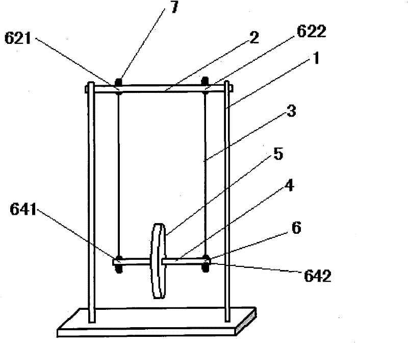
[0003] During the experiment, it is difficult to keep the heavy wheel moving up and down in the vertical plane during the rotation of such a rolling pendulum, and the heavy wheel is very easy to shake forward, backward, left, and right, which leads to the failure of the experiment. The reason is: the suspension of the heavy wheel and the rotation axis The different lengths of the ropes lead to the inclination of the rotating shaft, and the heavy wheel must shake forward, backward, left, and right while rotating.
In order to make the left and right ropes the same length, after tying one rope, the teachers carefully and carefully tie a knot on the other rope, but the knot of the rope will stretch about a few millimeters when it is tightened. The lengths of the two ropes are still inconsistent, and the heavy wheel still shakes left and right, which affects the progress of the experiment

Method used


Image

  • Rolling rope line winding method
  • Rolling rope line winding method
  • Rolling rope line winding method

Examples


Embodiment Construction

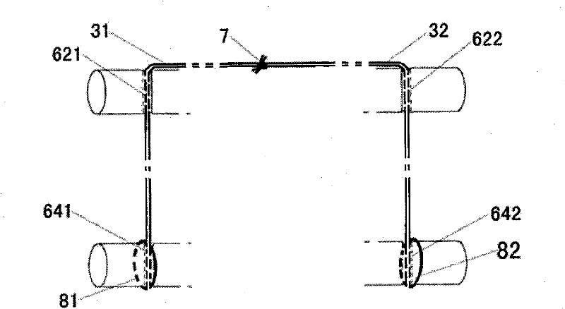
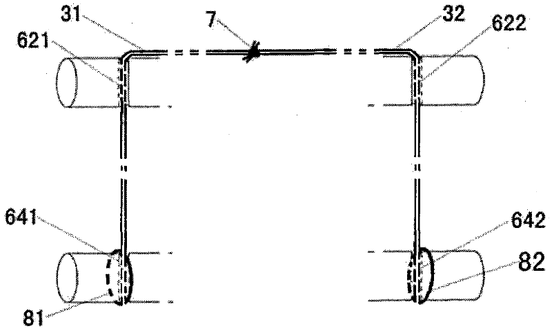
[0013] Such as figure 2 As shown, the folded end of the left rope 31 passes through the left eyelet 621 of the crossbeam and the left eyelet 641 of the rotating shaft in turn, and then reverses to form the left rope coil 81, which is then placed on the left end of the rotating shaft 4;

[0014] The folded end of the right rope 32 passed through the right eyelet 622 of the crossbeam and the right eyelet 642 of the rotating shaft in turn, and then reversed to form the right rope coil 82, which is then placed on the right end of the rotating shaft 4;

[0015] The other ends of the left string 31 and the right string 32 are knotted with each other to form a string knot 7 and then connected together.


PUM


Abstract

The invention discloses a rope winding method of a rolling swing. The rolling swing comprises: a crossbeam with left and right holes, a rotating shaft with left and right holes, passing through the corresponding holes on the crossbeam and the rotating shaft to suspend the rotating shaft. The rope that gets up is characterized in that: said rope is two, is respectively left rope and right rope; The winding method of described left and right rope is divided into two steps: A, wear left and right rope respectively on corresponding In the hole: the folded end of the left rope is passed through the left hole of the beam and the left hole of the rotating shaft in turn, and then reversed to form a coil of the left rope, which is then sleeved on the left end of the rotating shaft; the folded end of the right rope is folded in half Pass through the right eyelet of the crossbeam and the right eyelet of the rotating shaft in turn, and then reverse to form the right rope coil and then sleeve it on the right end of the rotating shaft; B. Knot the other ends of the left and right ropes together. Just move the knotted position of the rope left and right to adjust the length of the left and right ropes to ensure the level of the rotating shaft and improve the experimental effect.

Description

Technical field [0001] The invention relates to a physics teaching instrument, in particular to a rolling rope structure. Background technique [0002] Such as figure 1 As shown, the rolling pendulum used in the existing physics teaching includes: a support 1, a beam 2 fixed horizontally by the support, a rotating shaft 4 suspended by a rope 3 below the cross beam 2, and a heavy wheel 5 fixed in the middle of the rotating shaft 4 . There are two holes 6 on both sides of the crossbeam 2, which are respectively the left eyelet 621 and the right hole 622 of the crossbeam; The rope 3 is divided into two left and right pieces. The left rope 31 passes through the left eyelet 621 of the crossbeam and the left eyelet 641 of the rotating shaft to form a rope knot 7, and the right rope 32 passes through the right eyelet 622 of the crossbeam and the right eyelet 642 of the rotating shaft to form a knot. Rope knot7. [0003] During the experiment, it is difficult to keep the heavy wh...

Claims


Application Information

Patent Timeline
IPC IPC(8): G09B23/10
Inventor 张静文
Owner 张静文
Why Eureka
Eureka Blog
Learn More