Light pressure demonstrating and measuring system based on fiber optical path

A measurement system and optical path technology, which is applied in the field of optical demonstration and measurement systems, can solve problems such as unsatisfactory demonstration effects, low success rate and stability of experiments, difficulties in light pressure demonstration and measurement, and achieve cost-effectiveness and practicality. , Experimental effect and success rate improvement, the effect of compact structure

Inactive Publication Date: 2016-04-27
FOSHAN UNIVERSITY
View PDF2 Cites 19 Cited by
  • Summary
  • Abstract
  • Description
  • Claims
  • Application Information

AI Technical Summary

Problems solved by technology

[0004] However, it is very difficult to demonstrate and measure light pressure, because under normal experimental conditions, the light pressure is only 10-6 ~ 10-7 N / m 2
However, since the discovery of lasers in the early 1960s, lasers emitted by high-power lasers have been used as light sources for light pressure experiments. However, some light pressure experiment systems have defects in the optical path, and the demonstration effect is not satisfactory. The experiment was successful. The efficiency and stability are not high. It is necessary to use a goniometer to measure the angular displacement of the suspension mirror to complete the measurement of the light pressure. The error caused by the human operation is sometimes unavoidable.

Method used


Image

  • Light pressure demonstrating and measuring system based on fiber optical path
  • Light pressure demonstrating and measuring system based on fiber optical path
  • Light pressure demonstrating and measuring system based on fiber optical path

Examples


Embodiment Construction

[0045] The preferred embodiments of the present invention will be described below in conjunction with the accompanying drawings. It should be understood that the preferred embodiments described here are only used to illustrate and explain the present invention, and are not intended to limit the present invention.

[0046] In the background art, the difficulties faced in realizing the light pressure demonstration and measurement have been mentioned. In order to solve the above-mentioned difficulties, the present invention designs a light pressure demonstration and measurement system based on optical fiber optical path.

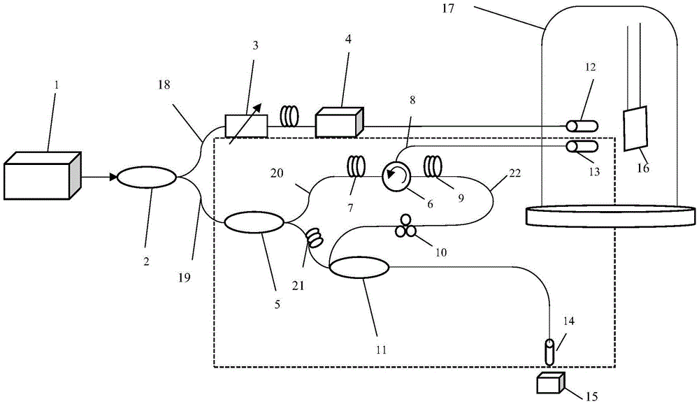
[0047] figure 1 A structural principle diagram of the system of the embodiment of the present invention is shown. Such as figure 1 As shown, the optical pressure demonstration and measurement system mainly includes a light source, a sheet 16 and a sheet support, an optical pressure demonstration optical path, an optical pressure measurement optical path, and ...


PUM


Abstract

The invention discloses a light pressure demonstrating and measuring system based on a fiber optical path. A light source is included, light emitted by the light source passes a first fiber coupler, the first fiber coupler transmits 90% of optical signals to a light pressure demonstrating part and 10% of optical signals to the light pressure measuring part, the light pressure demonstrating part comprises an attenuator, an optical switch, a collimator and a slice successively, the optical switch converts continuous laser into pulse laser, and the attenuator is adjustable. According to the invention, the flexibility of the light pressure demonstrating and measuring system based on the fiber optical path is improved, and requirements for the laser power, the detector flexibility and test environments of the system are lowered. The optical path is easy to adjust and compact in structure, the experiment effect and the success rate are both improved, and the power loss of the light source is reduced. The signal processing function is flexible, data is processed via a computer, and possible errors of manual measurement can be avoided.

Description

technical field [0001] The invention relates to an optical demonstration and measurement system, in particular to an optical pressure demonstration and measurement system based on an optical fiber optical path used in optics. Background technique [0002] In the 17th century, the German astronomer Kepler used the "pressure of sunlight" to explain the phenomenon that the tail of a comet always faces away from the sun. In the 19th century, the British physicist Maxwell calculated from the electromagnetic theory of light : The pressure produced by light being incident on a black body (an object that completely absorbs light) is p=S / c (S is the value of Poynting's vector, c is the speed of light), which predicts the existence of light pressure. In 1901, the Russian physicist Lebedev successfully eliminated the influence of the transport flow and radiation force on the experiment, and completed the measurement of the light pressure on the solid for the first time. The measured so...

Claims


Application Information

Patent Timeline
Patent Type & Authority Applications(China)
IPC IPC(8): G01J1/56
CPCG01J1/56
Inventor 任翔朱毅锵曹辉冯键铭罗志辉陈培宏
Owner FOSHAN UNIVERSITY
Why Eureka
Try Eureka