
wire clip

A wire clip and body technology, which is applied in the field of wire clips for grounding metal structures, can solve the problems of spending a lot of time and adding lost accessories.

Inactive Publication Date: 2011-12-14
MECATRACTION
View PDF9 Cites 3 Cited by
  • Summary
  • Abstract
  • Description
  • Claims
  • Application Information

AI Technical Summary

Problems solved by technology

[0008] Putting such a clip in place requires manipulation and assembly of multiple parts, which takes a significant amount of time for the installer and increases the risk of losing the fitting during the operation

Method used


Image

  • wire clip
  • wire clip
  • wire clip

Examples


Embodiment Construction

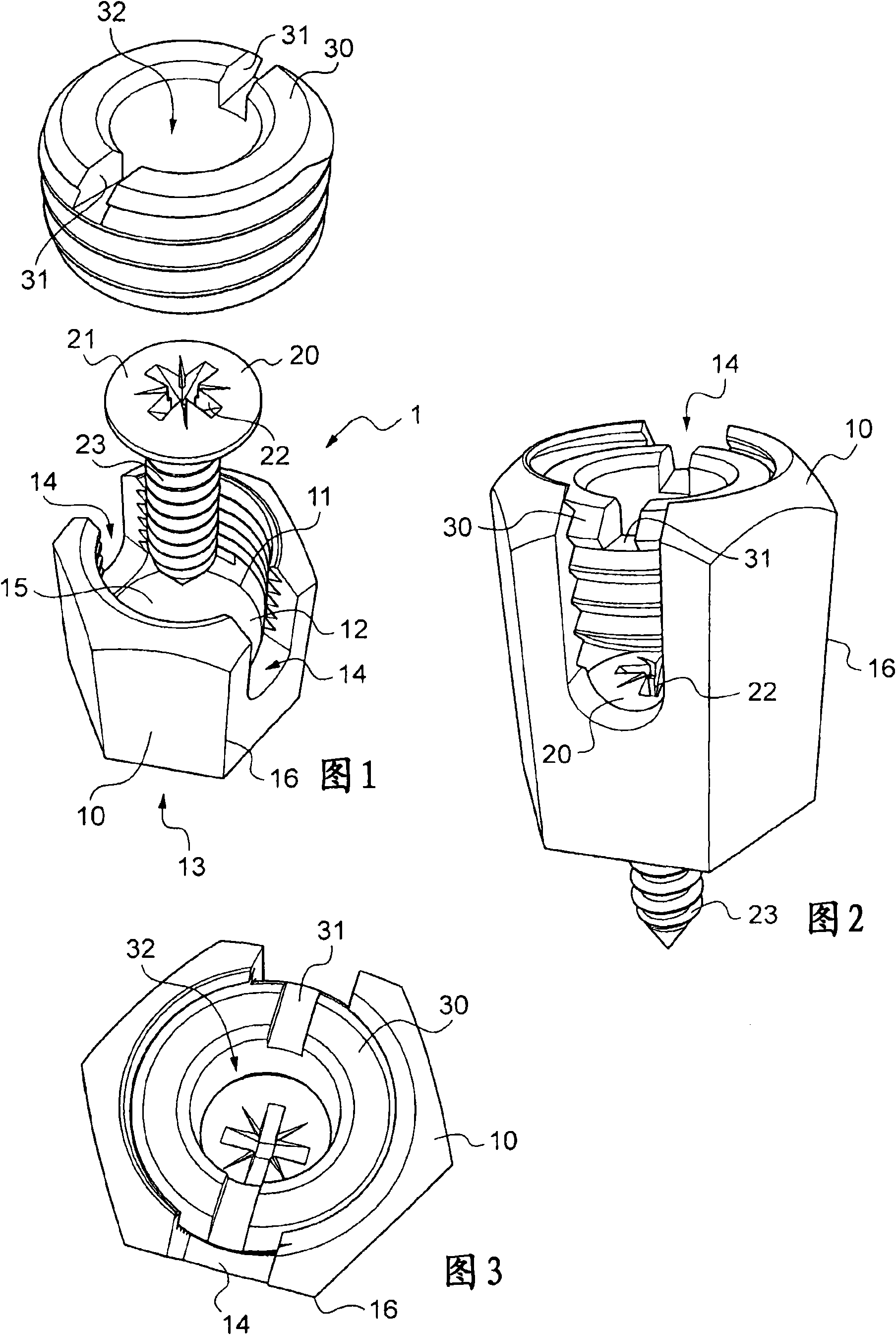
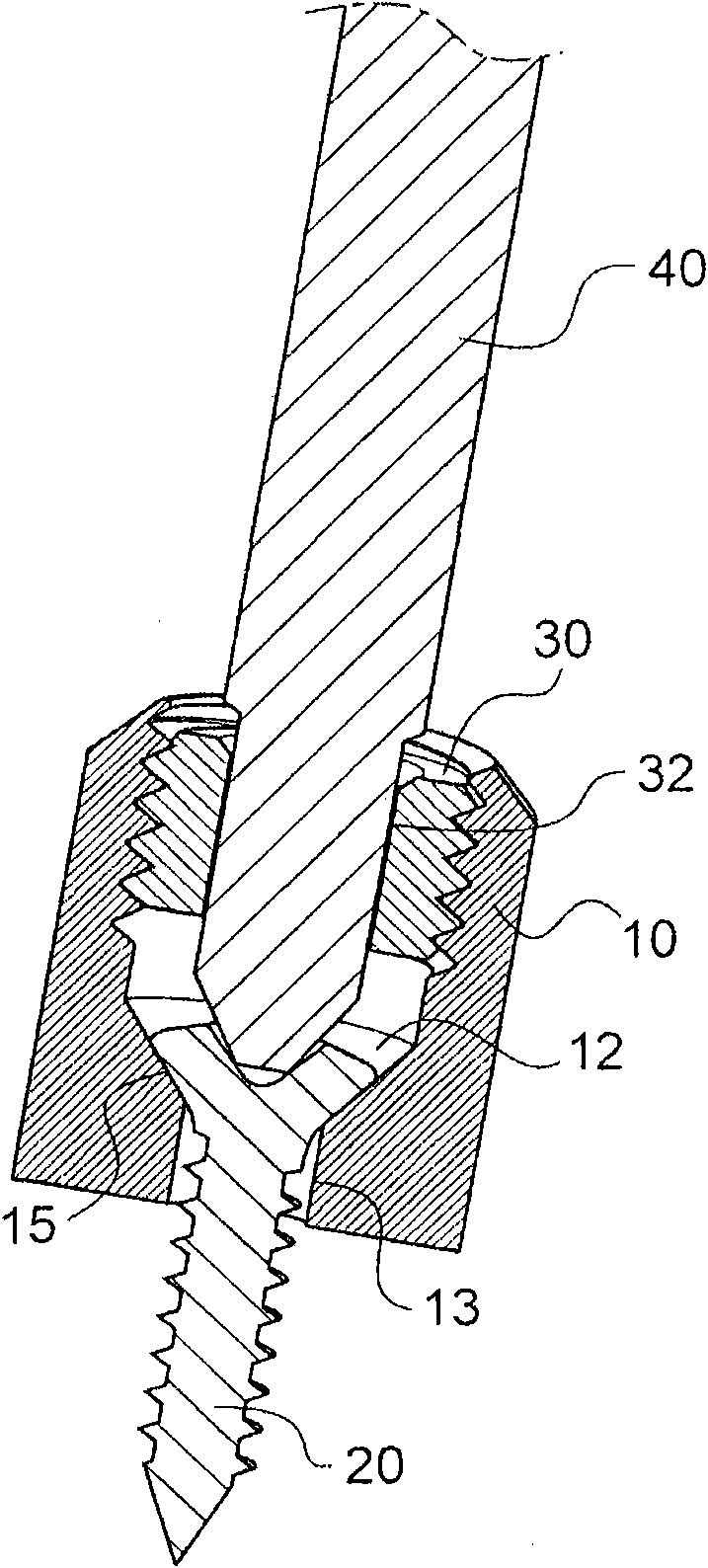
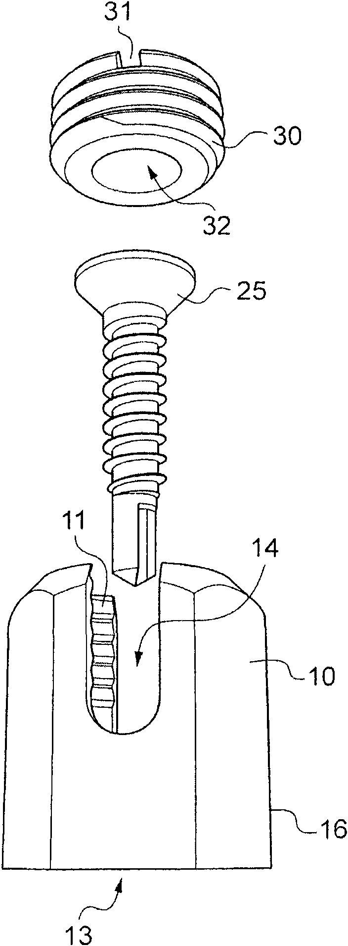
[0040] See attached figure 1 , the clamp 1 is used to ground a metal structure (not shown), and the clamp 1 includes a body 10 having a cylindrical cavity 11 with an internal thread, which is open at the upper end of the body and It is closed at the bottom 12 which has pierced holes 13 for the passage of screws 20 to fix the body 10 to the metal structure. Along the two generatrices of the cylindrical cavity 11, the body 10 has two through slots 14 facing each other for receiving ground wires (not shown).

[0041] The threaded plug 30 is adapted to helically engage with the internal thread of the cylindrical cavity 11 . The plug has two diametrically opposed cutouts 31 forming a configuration for the rotary drive of a flat-blade screwdriver, so that the plug grips a wire placed against the bottom of the slot 14 .

[0042] The screw 20 has a head 21 with a cross formation 22 for rotational drive and a threaded screw body 23 .

[0043] The plug 30 also has a central through h...


PUM


Abstract

The invention relates to a wire clamp, which is used to ground a metal structure. The wire clamp includes: a body (10), the body has a cylindrical cavity with an internal thread, and the cavity opens at the first end of the body. One end is closed by the bottom (12), which has a through hole (13). The hole is used for the passage of the screw (20). The screw is used to fix the body to the metal structure. The body is at least in the cavity with internal threads. One part has two through-slots facing each other, the through-slots are formed along the two busbars of the cylindrical cavity and open at the first end, and a threaded plug (30) with a rotary drive Constructed and intended to be helically engaged in the internal thread of a cylindrical cavity to clamp the core of the wire against the bottom of the through slot, the plug has a central through hole (32) for allowing a tool By, the tool is used to rotationally drive screws to secure the body to the metal structure.

Description

technical field [0001] The present invention generally relates to cord clips. [0002] More specifically, the present invention relates to clamps suitable for grounding metallic structures. Background technique [0003] A clamp for grounding the metal structure is adapted to be fastened in an electrically conductive manner to the metal part of the profiled part. They have clamping means for electrical connection to ground wire. Such clamps are used in particular for grounded metal structures such as aluminum photovoltaic panel modules and their supporting frames. [0004] To achieve the above objects, known clamps for grounding metallic structures comprise a body having a threaded tapped cylindrical cavity open at a first end of the body, the other end being closed by a bottom with a stab A perforation for the passage of a screw or pin used to secure the body to a metal structure. [0005] On a part of the tapped cavity, the body has two through slots facing each other f...

Claims


Application Information

Patent Timeline
IPC IPC(8): H01R4/28H01R4/30H01R43/00H01R43/027
CPCH01R4/66H01R4/32H01R4/36Y10T29/49117
Inventor T·洛佩E·热里
Owner MECATRACTION
Learn More