Drives for twin-screw extruders capable of driving rotation in the same direction

A twin-screw extruder, driving device technology, applied in the direction of transmission, gear transmission, mechanical equipment, etc., can solve problems such as load increase, achieve high torque and/or high speed transmission, realize torque and/or The effect of high-speed delivery

Inactive Publication Date: 2015-12-09
COPERION
View PDF5 Cites 0 Cited by
  • Summary
  • Abstract
  • Description
  • Claims
  • Application Information

AI Technical Summary

Problems solved by technology

The disadvantage of this drive is that the ever-increasing speed of the screw shaft required for industrial purposes leads to high radial acceleration forces acting on the planetary gear and thus to an increased load on the bearings
This increased load has a negative impact on the life of the drive, requiring a special bearing design which in turn leads to a more complex drive design

Method used


Image

  • Drives for twin-screw extruders capable of driving rotation in the same direction
  • Drives for twin-screw extruders capable of driving rotation in the same direction
  • Drives for twin-screw extruders capable of driving rotation in the same direction

Examples


Embodiment Construction

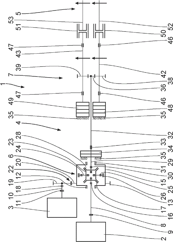
[0030] Refer below Figure 1-3 A first embodiment of the present invention will be described. The twin-screw extruder device 1 comprises a main drive motor 2 and an auxiliary drive motor 3 , through which a twin-screw extruder 5 is driven to rotate in the same direction via a drive device 4 .

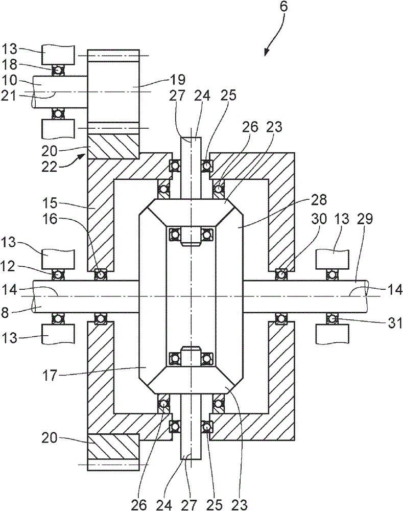
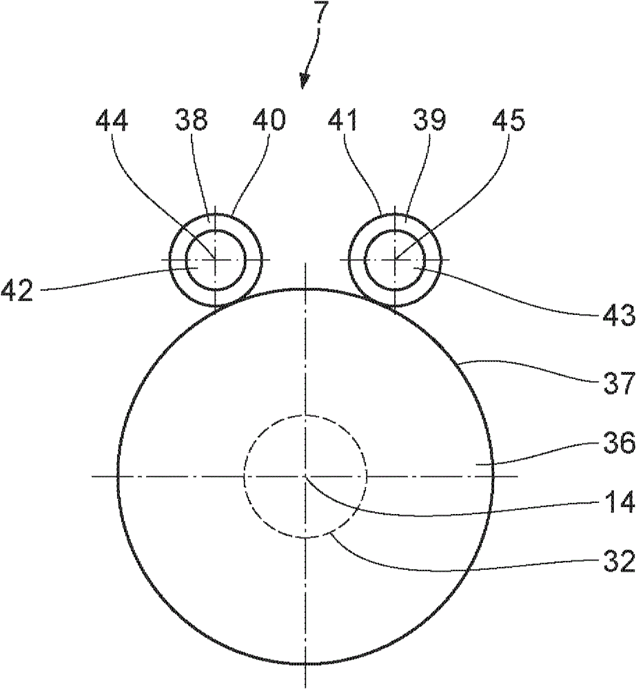
[0031] The drive 4 comprises a differential superposition transmission 6 and a downstream power distribution transmission 7 . The differential superposition transmission 6 comprises a first superposition transmission input shaft 8 connected to the main drive motor 2 via a coupling / coupling arrangement 9 . The differential superposition transmission 6 also comprises a second superposition transmission input shaft 10 connected to the auxiliary drive motor 3 via a second coupling 11 .

[0032] The input shaft 8 is mounted via radial bearings 12 in a transmission housing 13 and can be driven in rotation about a first axis of rotation 14 by the main drive motor 2 . Furthermore, the input ...


PUM


Abstract

The device (4) has an overriding drive (6) for superimposing drive power of drive motors, and overriding drive-input shafts (8, 10) rotatable by the motors. A power splitting transmission (7) is provided for branching drive power transferred to an overriding drive-output shaft (29). The transmission has two power splitting transmission-output shafts (42, 43) coupled with worm shafts (52, 53) of a twin screw extruder, where the drive is designed as a differential-overriding drive. A beveled wheel (28) is supported at a differential casing (15) of the drive in a rotatable manner. An independent claim is also included for a twin screw extruder arrangement comprising a drive device.

Description

technical field [0001] The invention relates to a drive for a twin-screw extruder capable of being driven in rotation in the same direction, the drive comprising: a superposition transmission for superimposing the drive power of two different drive motors and for A power distribution transmission for distributing drive power which has been superimposed on said superposition transmission output shaft, said superposition transmission comprising: two superposition transmission input shafts and a superposition transmission output shaft, the two superposition transmissions The input shaft can be driven in rotation by said two different drive motors; the power distribution transmission includes two power distribution transmission output shafts, which can be connected to the two screw shaft. Background technique [0002] DE19736549C2 discloses a drive for a twin-screw extruder which can transmit a power of more than 15000 kW and which can be adapted to the speed of the screw shaft...

Claims


Application Information

Patent Timeline
Patent Type & Authority Patents(China)
IPC IPC(8): B29C47/58B29C47/40B29C48/405B29C48/50
CPCB29C47/0801B29B7/46B29C47/0009B29C47/0803B29C47/0805B29C47/38B29C47/40B29C47/404B29C2947/9259B29C2947/92952B29C2947/9298F16H3/724F16H37/065B29C48/03B29C48/252B29C48/2522B29C48/2526B29C48/395B29C48/404B29C2948/9259B29C2948/92952B29C2948/9298B29C48/405
Inventor K·阿施巴歇A·卢科R·施莱歇S·韦尔布
Owner COPERION
Why Eureka
Try Eureka