New stud structure

A new type of stud technology, applied in the direction of rivets, can solve the problems that the stud structure 10 cannot be riveted in, and the riveting splines 110 are easily broken, and achieve the effect of easy riveting and thin riveting

Inactive Publication Date: 2011-12-21
SUZHOU MITAC PRECISION TECH
View PDF0 Cites 3 Cited by
  • Summary
  • Abstract
  • Description
  • Claims
  • Application Information

AI Technical Summary

Problems solved by technology

[0003] However, when riveting the stud structure 10, if the riveting teeth 110 of the stud structure 10 are designed thicker, the stud structure 10 cannot be riveted into the product 20; When the design is thin, the stud structure 10 is easily riveted into the product 20, but when the tensile force (in the direction indicated by the arrow) that the stud structure 10 needs to bear is large, the riveting splines 110 are easily broken

Method used


Image

  • New stud structure
  • New stud structure
  • New stud structure

Examples


Embodiment Construction

[0013] The present invention will be further described below in conjunction with the accompanying drawings.

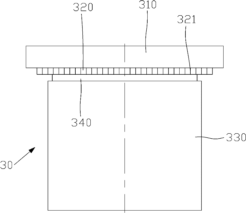
[0014] see image 3 As shown, it depicts a schematic diagram of the novel stud structure of the present invention. In this embodiment, the novel stud structure 30 of the present invention is applied to riveting products. The novel stud structure 30 includes successively smaller diameters. An anti-tension ring 310, a riveting spline 320, a cylinder 330 and a extrusion trough 340, the anti-tension ring 310, riveting spline 320, extrusion groove 340 and cylinder 330 are connected in sequence, The riveting flower tooth 320 is provided with a gear-shaped structure 321, and the thickness of the riveting flower tooth 320 is relatively thin, while the thickness of the tension ring 310 is relatively thick. In this embodiment, the riveting flower tooth 320 The thickness is 0.3 mm, and the thickness of the tension ring 310 is 1 mm.

[0015] When riveting this new stud structure...


PUM


Abstract

A new type of stud structure, which is applied to riveting products. The new type of stud structure includes a tension ring with successively smaller diameters, a riveting spline, a column and an extrusion groove. The force ring, the riveting flower teeth, the extruding groove and the column are sequentially connected, and the riveting flower teeth are provided with a gear-shaped structure. The riveting teeth of the novel stud structure of the present invention are relatively thin and easy to be riveted, and the new stud structure adds a pressure-resistant ring on the riveting teeth, and when the new stud structure bears a large pulling force, the riveting The flower teeth will not splinter.

Description

【Technical field】 [0001] The invention relates to a fastener structure, in particular to a novel stud structure. 【Background technique】 [0002] In metal products there are often products that require riveted studs, see figure 1 , which shows a schematic diagram of the existing stud structure. The existing stud structure 10 includes a riveting flower tooth 110 with successively smaller diameters, a cylinder 120 and an extrusion groove 130 located between the riveting flower tooth 110 and the cylinder 120. The riveting flower tooth 110 There is a gear-shaped structure 111 on it. see figure 2 As shown in , it shows a schematic diagram of the existing stud structure after riveting. The product 20 is provided with a screw hole (not shown in the figure), and the inner diameter of the screw hole is slightly larger than or equal to the diameter of the above-mentioned cylinder 120 , but smaller than the diameter of the above-mentioned riveting flower teeth 110 . When riveting ...

Claims


Application Information

Patent Timeline
IPC IPC(8): F16B19/04
Inventor 王坚
Owner SUZHOU MITAC PRECISION TECH
Why Eureka
Try Eureka