Nut cap riveting die

A technology for riveting molds and caps, which is applied in metal processing equipment, forming tools, manufacturing tools, etc., can solve the problems of inconvenient positioning of caps and difficult riveting, and achieve the effects of simple structure, good return effect and uniform force

Inactive Publication Date: 2013-03-27
昌辉汽车电器(黄山)股份公司
View PDF6 Cites 3 Cited by
  • Summary
  • Abstract
  • Description
  • Claims
  • Application Information

AI Technical Summary

Problems solved by technology

[0003] The purpose of the present invention is to provide a cap riveting die, which solves the problem that the existing riveting die moves riveting from top to bottom, the cap at the end of the workpiece is inconvenient to locate, and the riveting is difficult

Method used


Image

  • Nut cap riveting die
  • Nut cap riveting die
  • Nut cap riveting die

Examples


Embodiment Construction

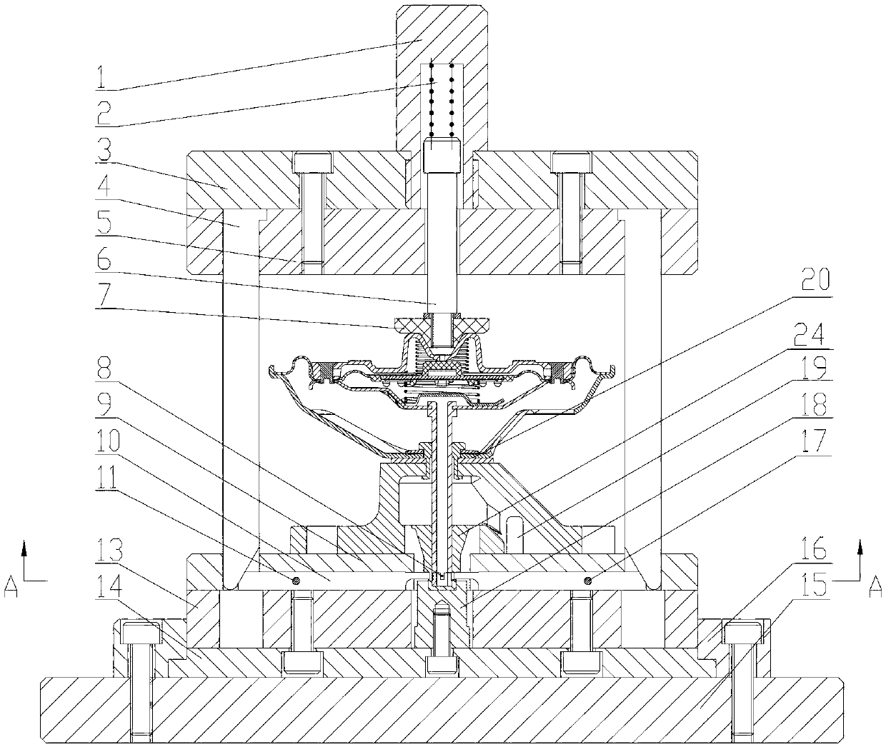
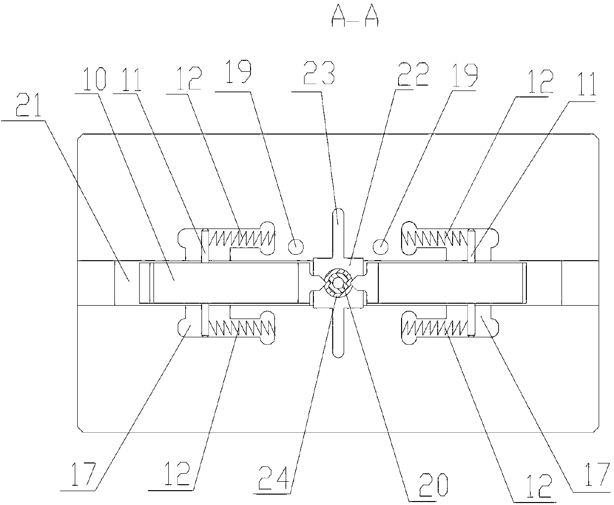
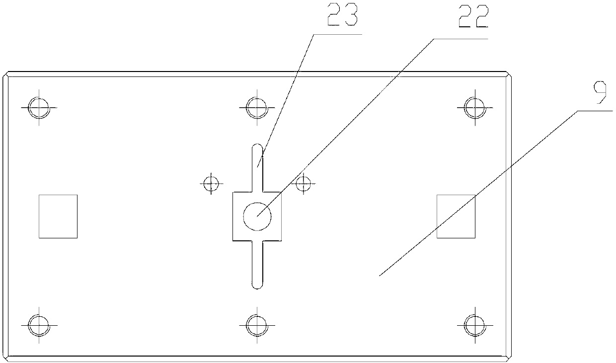
[0017] Examples such as Figures 1 to 3 Shown, a kind of cap riveting die comprises patrix, lower die, and lower die comprises base plate 15, the supporting plate 14 that is fixed on the base plate 15 by guide plate 16, the backing plate 13 that is fixed on the supporting plate 14 by bolt, is installed on The positioning plate 9 on the backing plate 13; the side of the positioning plate 9 in contact with the backing plate 13 is provided with a rectangular groove 21, and the positioning plate 9 is located in the middle of the rectangular groove 21 and has a through hole 22 for placing the workpiece 20; In the rectangular groove 21 and on both sides of the through hole 22, a punch 10 is respectively installed; two stop grooves 17 vertical to the rectangular groove 21 are also arranged on the positioning plate 9, and the width of the stop groove 17 is the same as that of the punch. The stroke of 10 is adapted; the described punch 10 is provided with a cylindrical pin 11, and the ...


PUM


Abstract

The invention discloses a nut cap riveting die which comprises an upper die and a lower die, wherein the lower die comprises a positioning board arranged on a base plate; a rectangular groove is arranged in one surface, which is in contact with the base plate, of the positioning board,,and a through hole for placing a workpiece is arranged in a middle position of the rectangular groove of the positioning board; plunger chips are respectively arranged in the rectangular groove and positioned in two sides of the through hole; a plunger chip compressed spring is arranged between each plunger chip and the positioning board; inclined wedges matched with the plunger chips are arranged on the upper die, and the inclined wedges enable the plunger chips to extrude the workpiece through extruding the plunger chip via the tail ends for realizing riveting. The nut cap riveting die has a simple structure, realizes riveting of a nut cap by driving the plunger chips to horizontally move through vertical movement of the inclined wedges, is convenient for riveting, is safe and reliable, facilitates the positioning of the workpiece and the nut cap, and can be widely applied to the field of riveting of the end part of the workpiece.

Description

technical field [0001] The invention relates to a riveting die, in particular to a cap riveting die. Background technique [0002] Usually, in the circular riveting process, the riveting head is made into a 360° ring, which is set on the workpiece, and under the vertical pressure of the press, it moves back and forth in one direction to rivet. If some workpieces with complex structures such as: two large ends, small middle, and the riveting position is in the middle workpiece, when riveting, the riveting difficulty will be greatly improved. Especially for the riveting of cylinders, it is more difficult to move riveting in the vertical direction. Contents of the invention [0003] The purpose of the present invention is to provide a cap riveting die, which solves the problem that the existing riveting die moves riveting from top to bottom, the cap at the end of the workpiece is inconvenient to locate, and the riveting is difficult. [0004] The technical solution adopted ...

Claims


Application Information

Patent Timeline
IPC IPC(8): B21D37/10
Inventor 王进丁王正成朱排进李宏志
Owner 昌辉汽车电器(黄山)股份公司
Why Eureka
Try Eureka