Liquid crystal television receiver

a television receiver and liquid crystal technology, applied in the field of liquid crystal television receivers, can solve the problems of inability to perform stable tilting movement, inability to stably support the image display portion in a static manner, etc., and achieve the effects of improving strength, simple structure and high strength

Inactive Publication Date: 2005-04-14
ORION ELECTRIC CO LTD
View PDF8 Cites 3 Cited by
  • Summary
  • Abstract
  • Description
  • Claims
  • Application Information

AI Technical Summary

Benefits of technology

[0023] The present invention forms a hinge portion from a pair of left and right hinge portions which are assembled together to form an integral hinge portion, according to which the formed hinge portion has a simple structure and improved strength. Therefore, the present invention provides a liquid crystal television receiver in which the direction of the liquid crystal panel can be adjusted appropriately to any viewing angle with freedom.
[0024] Since the shapes of the left and right hinge portions are plane symmetric, it is possible to form the front and rear directions of the equipment with two layered members by assembling the left and right hinges together, according to which a hinge portion of a liquid crystal television receiver having high strength can be provided.
[0025] Since the hinge portion is composed by assembling a pair of left and right hinge portions, the left and right hinge portions can be easily riveted (fastened for example by pressing and widening an end of a pin) from the inner side of the pivoting portion and the flat-head portion of the pin can be disposed on the outer side of the pivoting portion, so the width of the hinge portion can be formed small. Furthermore, by pivotally fastening the pivoting portion via riveting, the television receiver body can be tilted more freely within larger tilt angles and statically held at any desired angle.
[0026] Moreover, since a biasing means for biasing the swing portion is attached to the stand portion so as to bias the swing portion rearward by the biasing means when the television receiver body is tilted frontward, the rotational forces required for tilting the television receiver body frontward and rearward can be substantially equalized, and the television receiver body can be tilted in a stable fashion. Thus, the present invention enables to provide a liquid crystal television receiver having an advantageous quality and capable of preventing the receiver from turning over when the tilting operation of the television receiver body is performed by a rapid motion.
[0027] Furthermore, since the biasing means is composed of a mounting plate fixed to the stand portion and an engagement portion formed integrally with the mounting plate and engaged with the swing portion, the present invention enables to provide a liquid crystal television receiver that is cost-effective without having to use expensive coil springs and the like.

Problems solved by technology

Such pivoting means suffered the drawback of the hinge portion being loosened after long termuse of the equipment during which the tilting operation is repeated, and in some cases it became impossible to stably support the image display portion in a static manner.
However, this will not reduce the width of the hinge portion, and since the rigidity in the twisting direction of the pair of independent hinge members is weak, stable tilting movement cannot be performed if a twisting force is added when tilting the equipment.

Method used


Image

  • Liquid crystal television receiver
  • Liquid crystal television receiver
  • Liquid crystal television receiver

Examples


embodiment 2

[0067] [Embodiment 2]

[0068] Next, Embodiment 2 of the present invention will be described. FIG. 12 is an exploded perspective view showing a hinge portion according to Embodiment 2 of the present invention. FIG. 13 is an exploded perspective view showing the state in which a biasing means removed. FIG. 14 is an explanatory view showing a liquid crystal television receiver. FIG. 15 is an enlarged cross-sectional view showing the main part of the hinge portion.

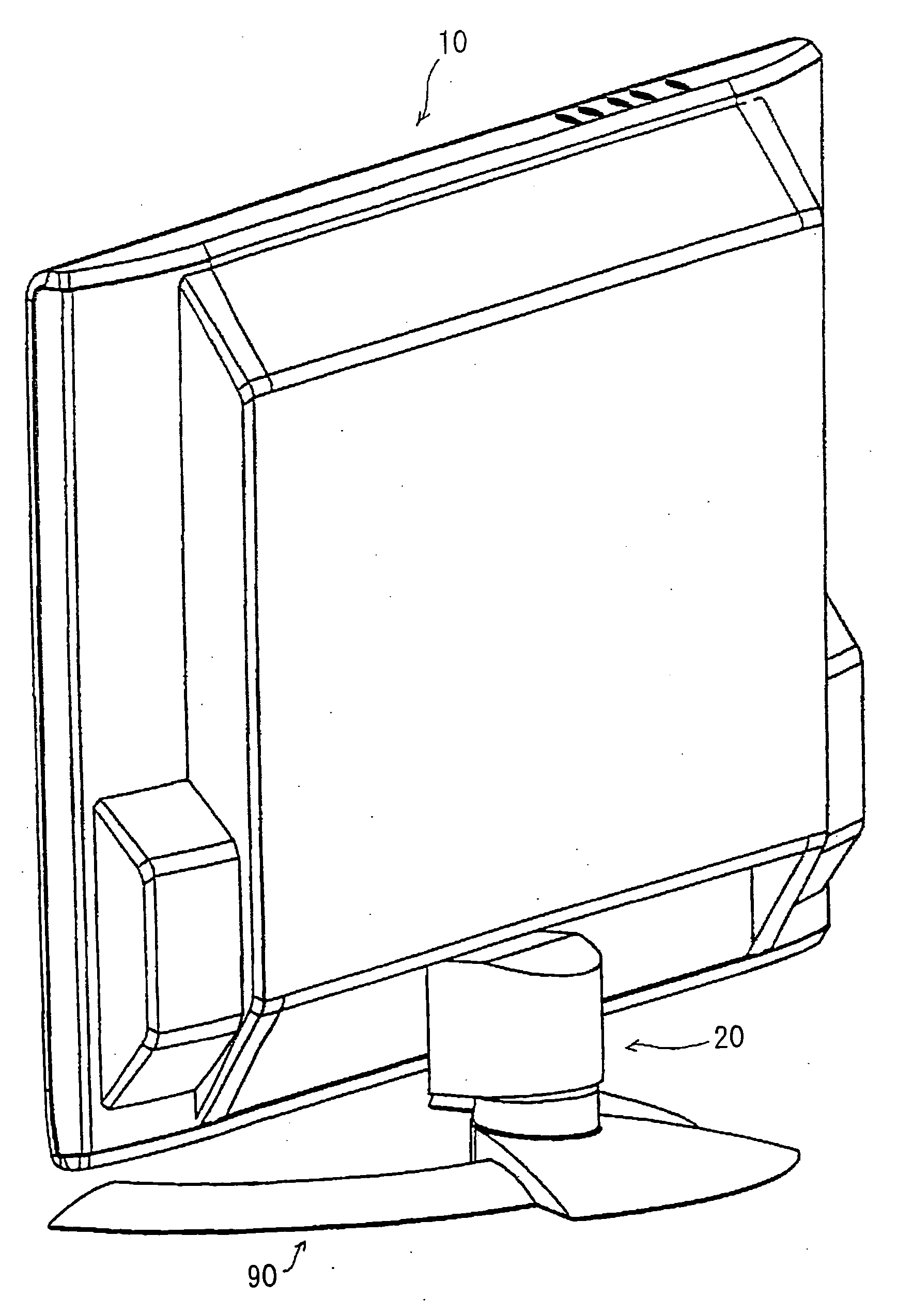
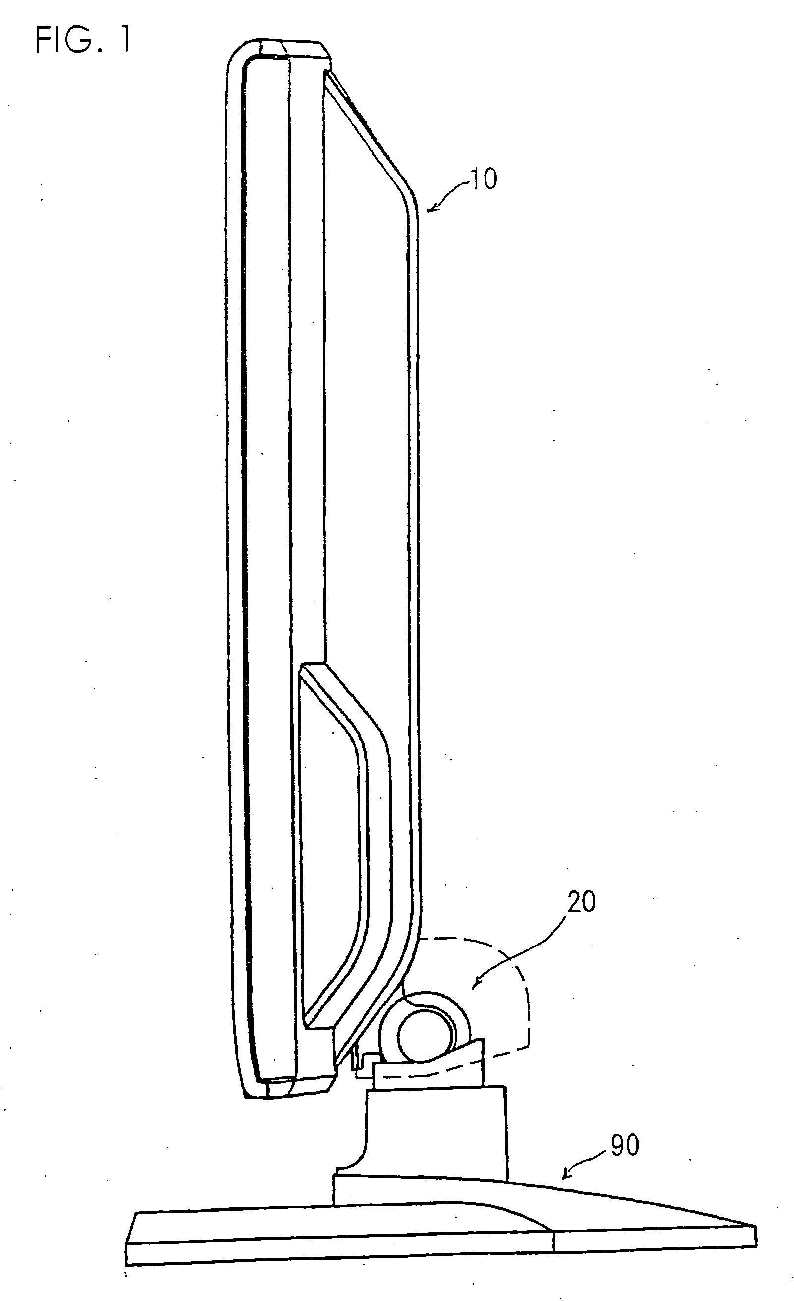
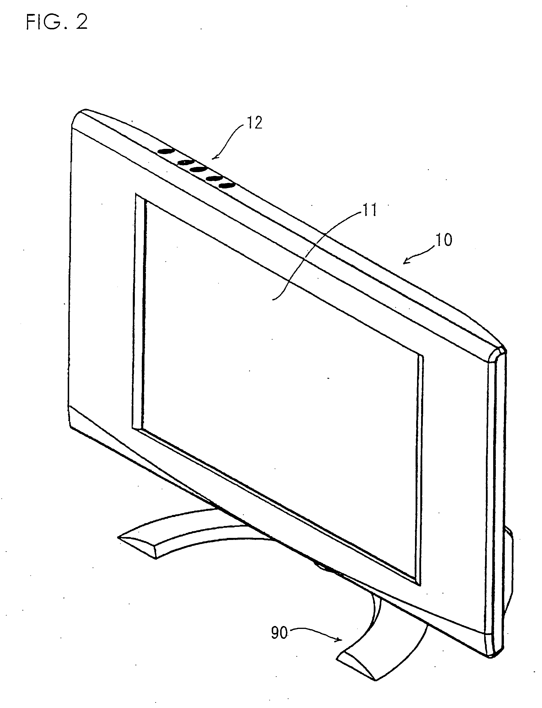
[0069] The present embodiment is equivalent to Embodiment 1 except for the biasing means, so the same members as Embodiment 1 are denoted with the same reference numbers and the detailed descriptions thereof are omitted. The television receiver body 10 according to Embodiment 2 is large sized and heavy, equipped with a large liquid crystal panel display portion 11 having a screen size of 20 inches or larger.

[0070] The biasing means is composed of a mounting plate 80 for fixture to a stand portion 71, and an engagement portion ...


PUM


Abstract

The invention provides a liquid crystal television receiver, a liquid crystal display of a desktop computer and the like, which is equipped with a pivoting means capable of statically maintaining the image display portion stably with the hinge portion prevented from being loosened even after performing tilting operation repeatedly for a long period of time. The invention provides a liquid crystal television receiver comprising a television receiver body equipped with a liquid crystal panel and a control unit, which is pivotally supported on a leg portion so as to enable tilting of the television receiver body, wherein a hinge portion pivotally supporting the television receiver body in a tiltable manner is composed of a pair of left and right hinge portions, the left and right hinge portions are respectively composed of a stand portion attached to the leg portion and a swing portion attached to the television receiver body, and the left and right hinges are assembled to form an integral hinge portion.

Description

[0001] The present application is based on and claims priority of Japanese patent applications No. 2003-339644 filed on Sep. 30, 2003 and No. 2004-54289 filed on Feb. 27, 2004, the entire contents of which are hereby incorporated by reference. BACKGROUND OF THE INVENTION [0002] 1. Field of the Invention [0003] The present invention relates to a liquid crystal television receiver in which a television receiver body equipped with a liquid, crystal panel and a control unit is pivotally supported on a leg portion in a tiltable fashion. [0004] The present invention is described using a liquid crystal television receiver as an example of the preferred embodiment of the invention, but it is applicable to liquid crystal displays of desk top personal computers and the like. It is also obviously applicable to any type of hinge structure bearing a pivoting movement. [0005] 2. Description of the Related Art [0006] Liquid crystal television receivers or liquid crystal displays of desk top person...

Claims


Application Information

Patent Timeline
Patent Type & Authority Applications(United States)
IPC IPC(8): F16M11/10H04N5/64G09F9/00
CPCF16M2200/08F16M11/10
Inventor UCHIZONO, TATSUYASHIMOSHITA, KENJI
Owner ORION ELECTRIC CO LTD
Why Eureka
Try Eureka