Sintering machine trolley grate pressing device

A technology of a pressing device and a machine trolley, which is applied to the furnace type, furnace, lighting and heating equipment, etc., can solve the problems of increasing air leakage from the side rails of the trolley, affecting the normal production of the sintering machine, and increasing the air leakage rate of the sintering machine. , to achieve the effect of reduced workload, simple structure and convenient transformation

Inactive Publication Date: 2011-12-21
SHOUGANG CHANGZHI IRON & STEEL
View PDF8 Cites 3 Cited by
  • Summary
  • Abstract
  • Description
  • Claims
  • Application Information

AI Technical Summary

Benefits of technology

This new design allows for better control over how well powdered materials (such as iron) are made by burning them down into metallic blocks or other shapes without causing any leaks during production. It also simplifies the process of replacing worn out parts with stronger ones while maintaining safety standards. Overall, this technology helps improve efficiency and productivity within the manufacturing industry.

Problems solved by technology

This technical problem addressed by this patented solution relates to how to securely attach or lock an end portion (a part called the top rod) of a grating assembly used for sinterer machines without causing any gaps where they shouldn't fit together properly.

Method used


Image

  • Sintering machine trolley grate pressing device
  • Sintering machine trolley grate pressing device
  • Sintering machine trolley grate pressing device

Examples


Embodiment Construction

[0009] Describe in detail below in conjunction with accompanying drawing.

[0010] as the picture shows:

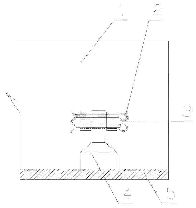
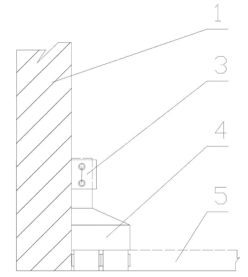
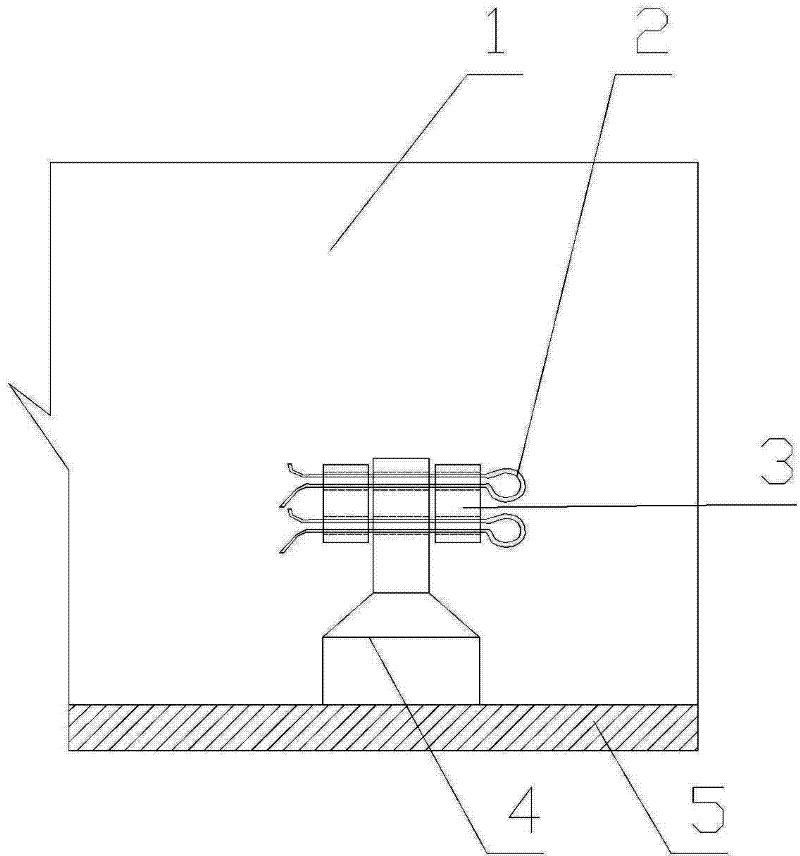
[0011] The steel briquetting groove 3 is welded on the inner side of the sintering machine trolley railing 1, and the briquetting groove 3 has two holes; For two holes with the same distance, the bottom of the briquetting block 4 compresses the grate bar 5, and the upper part of the briquetting block 4 is stuck in the slot 3, and the briquetting block is fixed by passing through the slot and the briquetting block through two cotter pins 2.

[0012] Beneficial effects: the advantage of the present invention is that the briquetting block is fixed inside the railing of the trolley, avoiding the opening of the railing, and can reduce the air leakage rate of the sintering machine; the assembly work of the grate bar and the briquetting block is all completed inside the trolley, and the replacement of the grate bar The workload is reduced; two steel cotter pins are used, the pr...


PUM


Abstract

The invention discloses a grate bar pressing device for a sintering machine trolley, which is to weld a steel briquetting groove on the inner side of the sintering machine trolley railing, and fix the briquetting block in the groove through two cotter pins. Compress the grate bar at the bottom. The advantage of the present invention is that the briquetting block is fixed inside the railing of the trolley, avoiding the opening of the railing, and can reduce the air leakage rate of the sintering machine; the assembly work of the grate and the briquetting is all completed inside the trolley, and the workload of replacing the grate is reduced ;Using two steel cotter pins, the pressing block is fixed more securely, and the shedding loss is reduced; the structure is simple, and the existing trolley can be easily modified.

Description


Claims


Application Information

Patent Timeline
Owner SHOUGANG CHANGZHI IRON & STEEL
Why Eureka
Try Eureka