
Atomic oscillator

A technology of atomic oscillators and metal atoms, applied in electrical components, automatic power control, etc., can solve problems such as reduced number of atoms, decrease in light energy level, deterioration, etc.

Inactive Publication Date: 2011-12-21
SEIKO EPSON CORP
View PDF4 Cites 7 Cited by
  • Summary
  • Abstract
  • Description
  • Claims
  • Application Information

AI Technical Summary

Problems solved by technology

[0006] However, the prior art disclosed in Patent Document 1, such as Figure 7 As shown in (B), by the frequency f generated by the current drive circuit 0 (=v / λ 0 : v is the speed of light, λ 0 is the central wavelength of the laser), the drive current is equivalent to the energy difference ΔE between the first ground state energy level 33 and the second ground state energy level 34 12 The modulation frequency fm1 of 1 / 2 of the frequency is modulated, so that the semiconductor laser produces a frequency of f1=f 0 The first resonant light 31 and frequency of +fm1 are f2=f 0 The second resonant light 32 of -fm1 causes the gaseous alkali metal atoms contained in the atomization cell to generate the EIT phenomenon
In addition, although in the EIT phenomenon, the greater the number of alkali metal atoms contained in the atomization cell, the greater the number of atoms contributing to the EIT phenomenon, and thus the greater the energy level of light that can be detected by the photodetector , but due to the demand for miniaturization and low consumption in recent years, when the number of alkali metal atoms contained in the atomization pool decreases, the number of atoms that contribute to the EIT phenomenon will also decrease, and there will be detected The problem that the energy level of light decreases and causes S / N deterioration

Method used


Image

  • Atomic oscillator
  • Atomic oscillator
  • Atomic oscillator

Examples


Embodiment Construction

[0053] Hereinafter, the present invention will be described in detail using the illustrated embodiments. However, the scope of the present invention is not limited to the embodiment unless there is a special description of the structural elements, types, combinations, shapes, and relative arrangement thereof described in the embodiment, and are merely illustrative examples.

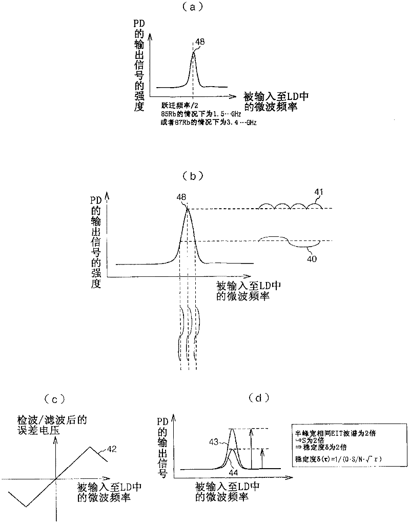
[0054] figure 1 This is a diagram for explaining the basic operation of the EIT phenomenon. First, when the power of the device is turned on, the center wavelength setting section 18 will set the center wavelength of the light source (LD) 1 so that image 3 The output of the photodetector (PD) 3 becomes maximum (refer to figure 1 (a)). When amplifying the EIT signal 48, it will be obtained as figure 1 This signal in (b). That is, when the waveform 40 is in the unlocked state, the center frequency of the phase modulation is shifted from the peak of the EIT signal 48 , and the output of the amplifie...


PUM


Abstract

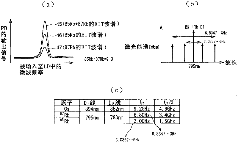
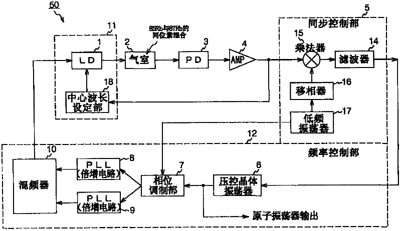
The invention provides an atomic oscillator which improves S / N by improving energy level of light absorbed by a photodetector. The atomic oscillator (50) mainly includes a cell (2) containing a mixture gas of alkali metal atoms and isotopes of the alkali metal atoms, a light source (LD) (1) that has coherency and irradiates the gas with lights including a first resonant light pair having two different frequency components for one center frequency and a second resonant light pair having two different frequency components for one center frequency, a photo detector (PD) (3) that generates a detection signal corresponding to intensity of light passing through the gas, and a frequency control part (12) that controls, based on the detection signal, frequencies of the first resonant light pair to cause an electromagnetically induced transparency phenomenon to occur in the alkali metal atom and controls frequencies of the second resonant light pair to cause the electromagnetically induced transparency phenomenon to occur in the isotope of the alkali metal atom.

Description

technical field [0001] The present invention relates to a method of controlling a light source of an atomic oscillator, and more particularly, to a light source of an atomic oscillator for stabilizing absorption trapping due to variable absorption gain of the atomic oscillator method of control. Background technique [0002] The atomic oscillator applying the electromagnetically induced transparency method (also called the EIT (Electromagnetically Induced Transparency) method, CPT (Coherent Population Trapping) method) is an oscillator that utilizes the following phenomenon (EIT phenomenon), that is, when the base When metal atoms are simultaneously irradiated with two types of resonance light having different wavelengths, the absorption of the two types of resonance light stops. Therefore, it is very important to obtain the EIT phenomenon stably. [0003] It is known that the interaction mechanism between the alkali metal atom and the two resonant lights can be as Figure...

Claims


Application Information

Patent Timeline
Patent Type & Authority Applications(China)
IPC IPC(8): H03L7/26
CPCH03L7/26
Inventor 牧义之吉田啓之田中良明
Owner SEIKO EPSON CORP
Learn More