Polar transmitter

A polar coordinate and transmitter technology, applied in electrical components, transmission systems, etc., can solve the problems of high processing complexity and increase the complexity of correcting delay errors, achieve high-speed delay compensation, and solve the deterioration of polar coordinate performance. Effect

Inactive Publication Date: 2011-12-21
UNIV OF ELECTRONICS SCI & TECH OF CHINA
View PDF4 Cites 20 Cited by
  • Summary
  • Abstract
  • Description
  • Claims
  • Application Information

AI Technical Summary

Problems solved by technology

However, the fractional delay requires interpolation processing or increased sampling rate, whic

Method used


Image

  • Polar transmitter
  • Polar transmitter
  • Polar transmitter

Examples


Embodiment

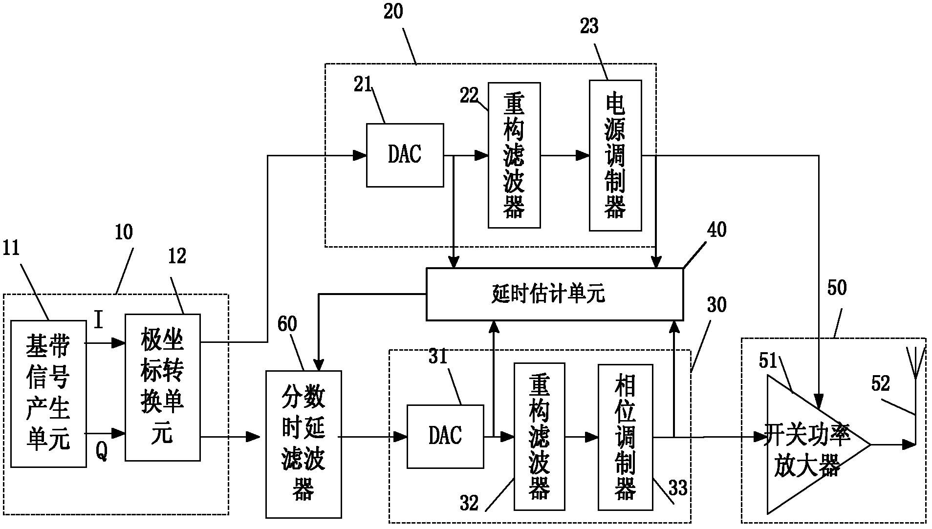
[0021] Such as image 3 As shown, the polar coordinate generating unit 10 includes a baseband signal generating unit 11 and a polar coordinate converting unit 12 . The generated I and Q signals of the baseband signal generation unit 11 are processed by the polar conversion unit 12, and the I and Q signals are converted from Cartesian coordinates to polar coordinates (ρ, θ signals) through the polar conversion unit 12, and ρ is a digital amplitude information, θ is the digital phase information: ρ ( t ) = I 2 ( t ) + Q 2 ...


PUM


Abstract

The invention provides a polar coordinate transmitter, which can meet the requirement of high speed rate at a low-speed clock frequency, i.e., compensate for integer time delay and fraction time delay under the condition of not increasing the sampling rate. The polar coordinate transmitter comprises a polar coordinate generating unit, an amplitude modulating unit, a phase modulating unit, a switch power amplifying unit, a time delay estimating unit and a variable fraction time delay filter, wherein the time delay estimating unit is used for estimating integer time delays of a phase channel and an amplitude channel on a time domain respectively, compensating for the integer time delays, estimating fraction time delays of the phase channel and the amplitude channel on a frequency domain respectively, adding an integer time delay error and a fraction time delay error between the phase channel and the amplitude channel to obtain a time delay error, and setting the variable fraction time delay filter according to the obtained time delay error; and the variable fraction time delay filter is used for performing time delay on a signal input into the phase channel and compensating for the time delay error between the phase channel and the amplitude channel.

Description

technical field [0001] The invention relates to wireless communication technology, in particular to the delay compensation technology of a transmitter. Background technique [0002] Polar transmitter combines power modulation technology and switching power amplifier technology. The polar coordinate transmitter includes a polar coordinate generation unit, an amplitude modulation unit, a phase modulation unit, a switching power amplification unit, and a polar coordinate generation unit, which are used to send the generated digital amplitude information to the amplitude modulation unit, and send the generated digital phase information to the The phase modulation unit; the phase modulation unit is used to convert the digital phase information into an analog signal, and generates a phase modulation signal with a constant envelope of radio frequency through phase modulation and outputs it to the input end of the switching power amplifying unit; the amplitude modulation unit is use...

Claims


Application Information

Patent Timeline
IPC IPC(8): H04B1/04
Inventor 游飞曹萍何松柏
Owner UNIV OF ELECTRONICS SCI & TECH OF CHINA
Why Eureka
Try Eureka