
Address assignment in the network

A network address, network technology, applied in the field of network nodes in the server role, can solve complex problems

Inactive Publication Date: 2011-12-21
TELEFON AB LM ERICSSON (PUBL)
View PDF11 Cites 9 Cited by
  • Summary
  • Abstract
  • Description
  • Claims
  • Application Information

AI Technical Summary

Problems solved by technology

One of the biggest challenges related to automatic configuration in dynamic networks is addressing - the automatic distribution and management of addresses in networks is a key part of autonomous it gets further complicated

Method used


Image

  • Address assignment in the network
  • Address assignment in the network
  • Address assignment in the network

Examples


Embodiment Construction

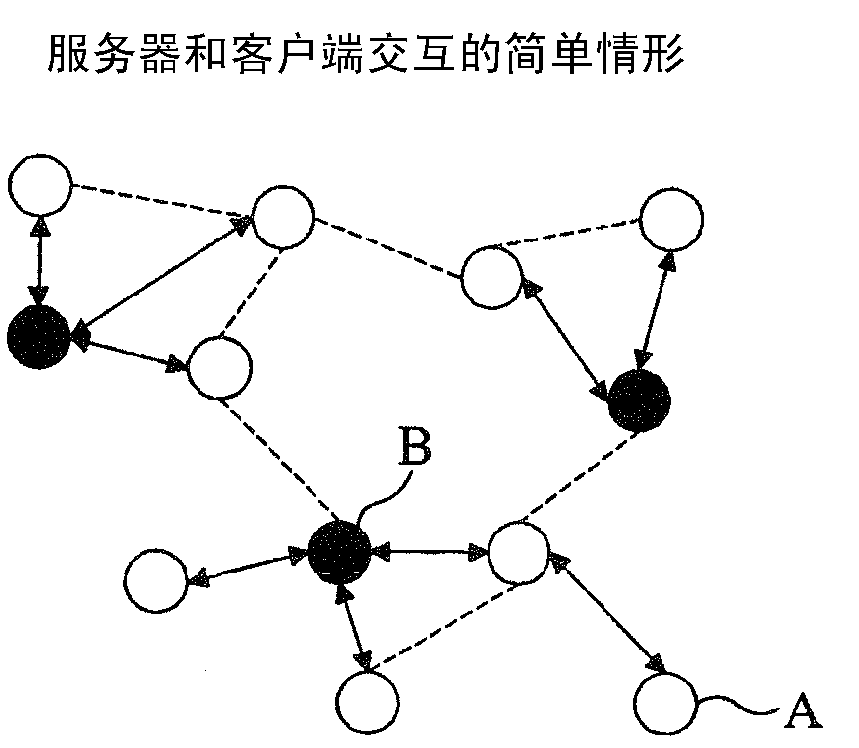
[0072] figure 2 A basic situation is illustrated where address distribution is handled by servers (black circles) distributed over the network. The server provides a valid address to each of its clients. Clients (white circles) do not necessarily need to be directly associated with the server (ie, through 1-hop association). When a new client establishes a link with the server through another client, let's say, the new client is at least 2 hops away from the server. exist figure 2 In , client A is 2 hops away from server B, and all other clients are directly associated (ie, associated by 1 hop) to their corresponding servers.

[0073] exist figure 2 In , the link between a server and its corresponding client is represented by a double-headed arrow. Links that do not represent the server-client hierarchy are drawn as dotted lines. In the first case, an "addressing relationship" is established between nodes, indicating that all management information for keeping nodes a...


PUM


Abstract

A method of address allocation in a network comprises determining, from negotiations between nodes, whether a first node shall assume a server role responsible for distribution and management of network addresses to clients. If this determination is made, the first node is provided with a pool of network addresses. The invention provides a method of dynamic re-allocation of address pools between servers of the network, in accordance with, for example, network requirements or traffic load.

Description

technical field [0001] The invention relates to address allocation in a network, in particular to dynamically allocating a network address pool to a network node having a server role responsible for distributing network addresses to nodes having a client role and managing the network addresses. Background technique [0002] The idea of ​​creating autonomous computer systems relies heavily on the concept of automatic configuration in computer networks. Establishing communication in dynamic networks without user intervention is one of the most important topics in next-generation computer networks. One of the biggest challenges related to automatic configuration in dynamic networks is addressing - the automatic distribution and management of addresses in networks is a key part of autonomous It gets further complicated. [0003] What is expected in future networks is for nodes to connect to and disconnect from the network without the user manually changing device configuration...

Claims


Application Information

Patent Timeline
IPC IPC(8): H04L29/14H04L29/12H04L69/40
CPCH04L29/06047H04L29/08306H04L29/14H04L69/40H04L67/104H04L29/12283H04L29/12226H04L61/2015H04L67/42H04L61/2061H04L61/5014H04L61/5061H04L67/1012H04L61/5007H04L67/01
Inventor 马丁·强森瑞纳耳多·戈梅斯朱迪斯·科尔纳贾迈勒·萨多克里卡多·德·奥利弗拉·施密特
Owner TELEFON AB LM ERICSSON (PUBL)
Learn More