A hydraulic lifting tower

A technology of hydraulic lifting and tower body, applied in the field of communication lifting tower, can solve the problems of troublesome removal, danger, troublesome installation, etc., and achieve the effect of small construction amount

Inactive Publication Date: 2011-12-28
ZHEJIANG JUJIANG STEEL IND +1
View PDF2 Cites 12 Cited by
  • Summary
  • Abstract
  • Description
  • Claims
  • Application Information

AI Technical Summary

Problems solved by technology

It is very troublesome to install, the amount of work is large, and it is relatively dangerous. At the same time, it is also very troublesome when it needs to be moved and removed.

Method used


Image

  • A hydraulic lifting tower
  • A hydraulic lifting tower
  • A hydraulic lifting tower

Examples


Embodiment Construction

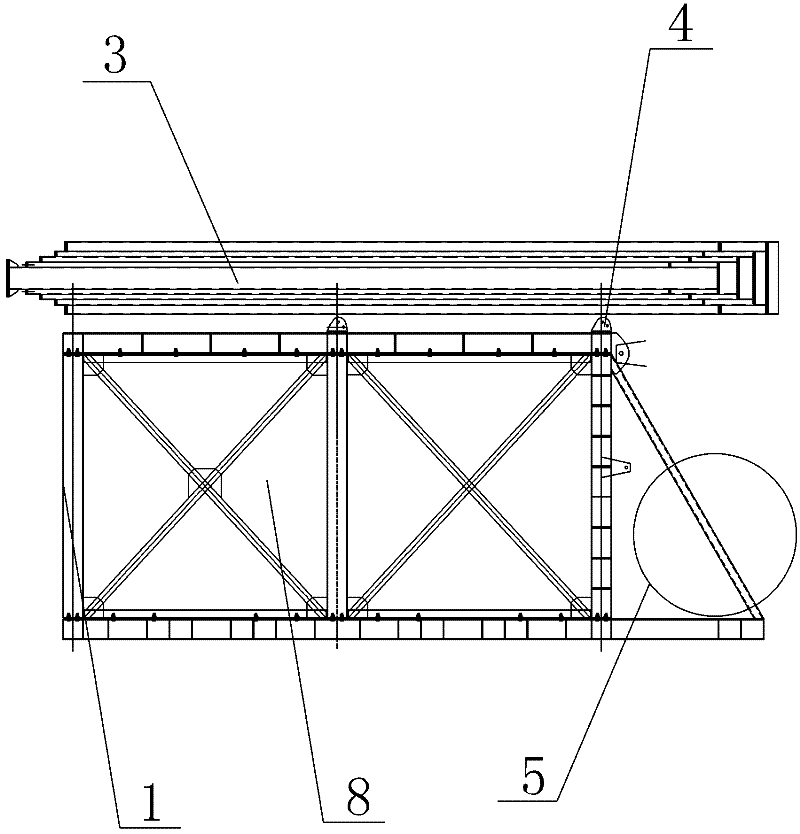
[0012] Such as Figure 1-3 , a hydraulic lifting tower, comprising a steel frame 1, the steel frame 1 is provided with a multi-section tower body 3, the tower body 3 and the steel frame 1 are flexibly connected by bolts 4, and the tower body is provided with sleeves The tubular hydraulic jack 5 and the casing hydraulic jack 5 drive the tower body 3 to lift.

[0013] After the tower body rises, each section of the tower body is fixed by pins 6. A machine room 8 is arranged on the steel frame 1 .

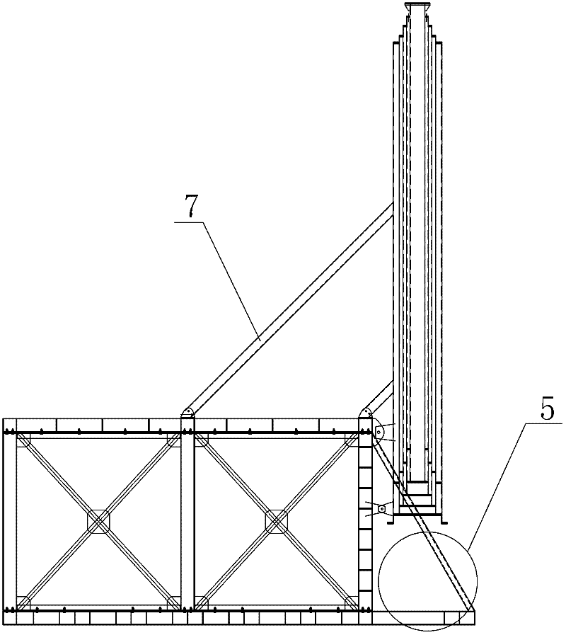
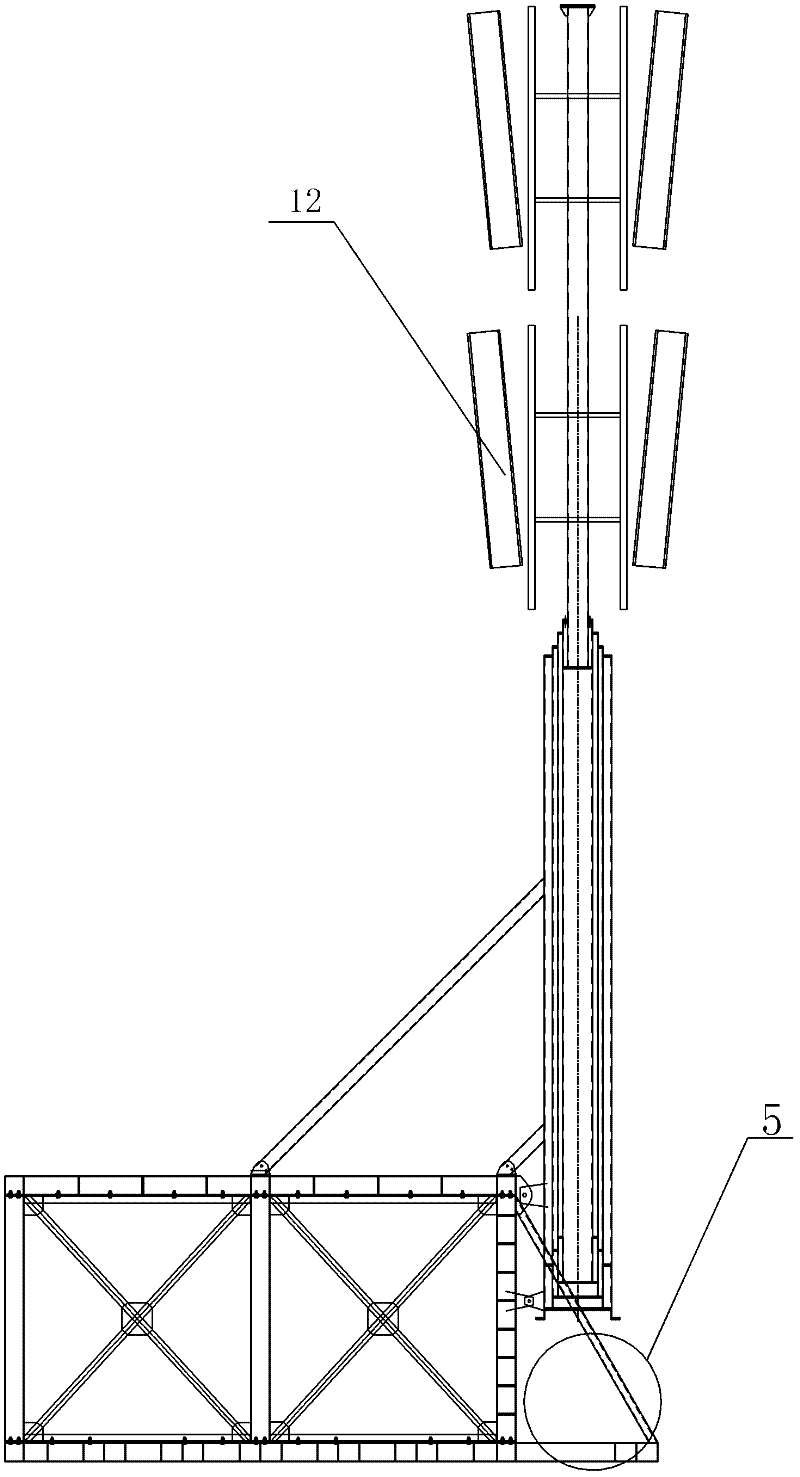
[0014] Such as Figure 4 , the tower body 3 of the lifting tower is a multi-section tower body. Before the tower body is raised up, the tower bodies of each section are socketed together, and the bottom section of the tower body is connected to the steel frame by bolts 4. The tower body is placed horizontally on the steel frame. When the tower body needs to be raised up, the tower body is rotated along the steel frame through the hinged bolts 4, and finally stands upright. After th...


PUM


Abstract

The invention discloses a hydraulic lifting tower, which comprises a steel frame. The steel frame is provided with a multi-jointed tower body. The tower body and the steel frame are flexibly connected by bolts. The casing type oil pressure top drives the tower body up and down. The tower body of the lifting tower of the present invention is connected with the steel frame by bolts. After the lifting tower is transported to the designated position, the tower body is erected and fixed on the steel frame with bolts, and then the lowermost tower body bottom A casing type hydraulic jack is installed at the end of the tower to push the tower up, and the towers of each section are fixed by pins, which is very convenient, the construction amount is small, and it is relatively safe; when it needs to be moved or dismantled, a jack is also installed on the top tower , It is more convenient to push down and store the tower body section by section through a jack.

Description

technical field [0001] The invention relates to a communication lifting tower. Background technique [0002] At present, communication towers are widely used in fields such as electric power, communication, broadcasting, and television signals. Communication towers generally install multi-section towers one by one, and finally install signal transmitting and receiving devices on the top of the tower. It is very troublesome to install, the project volume is relatively large, and it is relatively dangerous. At the same time, it is also very troublesome when it needs to be moved and removed. Contents of the invention [0003] The object of the present invention is to provide a hydraulic lifting tower that can be installed, moved and dismantled conveniently. [0004] The technical solution of the present invention: a hydraulic lifting tower, including a steel frame, the steel frame is provided with a multi-jointed tower body, the tower body and the steel frame are connected ...

Claims


Application Information

Patent Timeline
Patent Type & Authority Applications(China)
IPC IPC(8): E04H12/18
Inventor 李震
Owner ZHEJIANG JUJIANG STEEL IND
Why Eureka
Try Eureka