fan frame

A heat dissipation fan and fan frame technology, which is applied to parts of pumping devices for elastic fluids, non-variable pumps, machines/engines, etc., can solve the problem of inability to provide wire 84 positioning and protection measures, and inconvenient disassembly and use , unable to provide wires and other problems

Active Publication Date: 2011-12-28
SUNONWEALTH ELECTRIC MACHINE IND
View PDF11 Cites 7 Cited by
  • Summary
  • Abstract
  • Description
  • Claims
  • Application Information

AI Technical Summary

Problems solved by technology

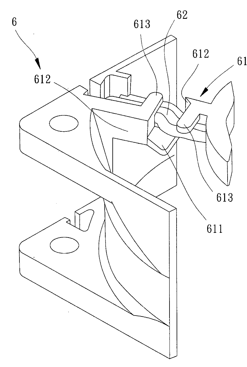
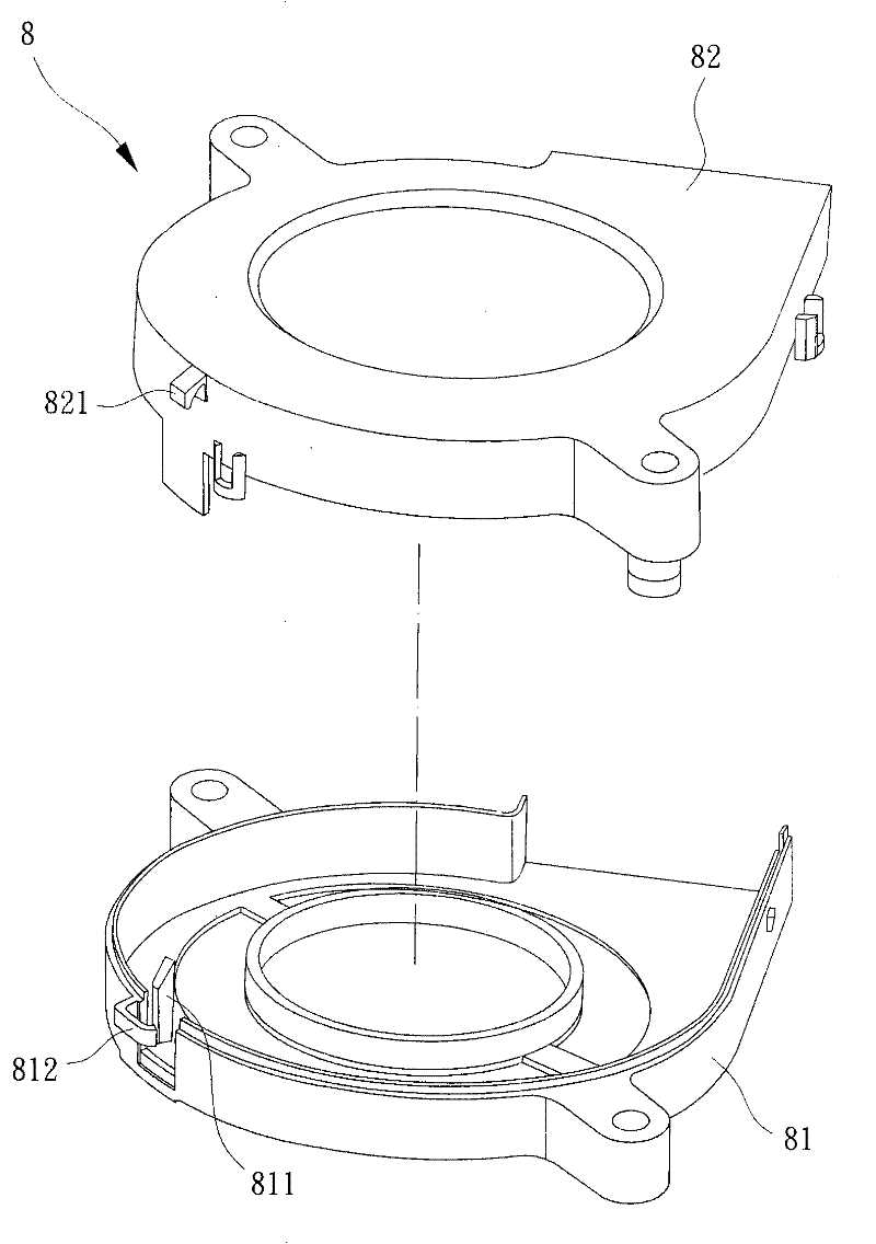
[0009] However, if Figure 4 As shown, the clamping space 83 of the above-mentioned third type of existing fan frame 8 can only be used for the electric wire 84 to pass through, and the positioning effect and anti-pull effect that the clamping space 83 can provide are still quite limited; moreover, the electric wire 84 is exposed and attached to the outer surface of the first frame body 81, which not only causes a lot of inconvenience in the installation and use of the existing fan frame 8, but also cannot provide good positioning and protection measures for the electric wire 84; The clamping space 83 of the frame 8 must be combined with the first frame body 81 and the second frame body 82 to form together. Therefore, it cannot be applied to the fan frame structure with only a single frame body design. limit, and also relatively increase the structural complexity and increase the overall manufacturing cost; moreover, the first frame body 81 and the second frame body 82 are not easy to disassemble after being combined, so there is also a lot of inconvenience in disassembly and use.
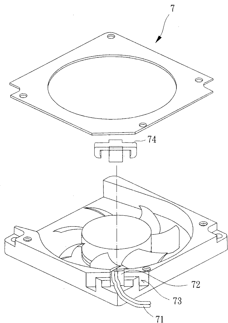
[0010] Generally speaking, the fan frames 6, 7, and 8 of the above-mentioned conventional cooling fans generally have the following disadvantages, for example: they cannot provide better positioning and anti-pull effects for the wires 62, 71, and 84, and the combination of the buckle 74 is stable. There are many shortcomings such as poor performance, high structural complexity, difficulty in developing and designing in the direction of thinning, and poor disassembly and assembly convenience, and there is a need for improvement.

Method used


Image

  • fan frame
  • fan frame
  • fan frame

Examples


Embodiment Construction

[0047] In order to make the above-mentioned and other objects, features and advantages of the present invention more comprehensible, the preferred embodiments of the present invention are specifically cited below, together with the accompanying drawings, as follows:

[0048] Please refer to Figure 5 and 6As shown, the fan frame of the cooling fan according to the preferred embodiment of the present invention includes at least a frame body 1 and a wire clamping member 2 . This frame body 1 has fan frame basic structures such as air inlet, air outlet and internal runner space, and this frame body 1 can be used for combining as motor 3 (such as Figure 6 Shown) or fan wheel and other components, in order to constitute a heat dissipation fan, the main technical features of the present invention will be further described below, the basic structure of the frame 1 and the assembly method of the heat dissipation fan can be understood by those with ordinary knowledge in the technical...


PUM


Abstract

The invention discloses a frame of a cooling fan, comprising a frame body and a wire clamp. The frame body is provided with a wiring region, a first fixing part and a second fixing part; the wiring region is provided with a first clamping part and a second clamping part which are respectively provided with a locating surface; the wire clamp is combined to the wiring region and is provided with a supporting part, the supporting part is provided with a supporting surface, and the supporting surface and the locating surface form a wire clamping space; in addition, the wire clamp is provided witha first tabling part and a second tabling part which are respectively clamped with the first fixing part and the second fixing part so as to ensure that the wire clamp and the frame body can be firmly combined.

Description

technical field [0001] The invention relates to a fan frame of a cooling fan, in particular to a fan frame of a cooling fan with a wire clamp. Background technique [0002] The fan frame of the existing cooling fan has an air inlet and an air outlet, and the air inlet and the air outlet communicate with the flow passage space inside the fan frame; thereby, the fan frame can be combined with a motor, and the motor is provided with a wire , the wire can be connected to an external power supply or a circuit board, so that the motor can be used to drive a fan wheel to rotate, thereby providing a heat dissipation effect. [0003] Generally speaking, the common axial-flow fan frames or blower fan frames on the market generally have a structural design that can be used to fix the electric wires of the motor, for example: [0004] Please refer to Taiwan Patent No. 502821 "Fan Cable Management Structure", which discloses the first conventional fan frame. Such as figure 1 As shown,...

Claims


Application Information

Patent Timeline
Patent Type & Authority Applications(China)
IPC IPC(8): F04D29/52
Inventor 洪银树修华远谢聪敏
Owner SUNONWEALTH ELECTRIC MACHINE IND
Why Eureka
Try Eureka