Implant planning for multiple implant components using constraints

A technology for implant components and planning, applied in the direction of joint implants, joint implants, applications, etc., to achieve high efficiency, less invasiveness, and improved proper placement

Active Publication Date: 2011-12-28
MAKO SURGICAL CORP
View PDF9 Cites 5 Cited by
  • Summary
  • Abstract
  • Description
  • Claims
  • Application Information

AI Technical Summary

Problems solved by technology

However, this requires capturing each point to map the cartilage surface, which is a timely and computationally involved procedure

Method used


Image

  • Implant planning for multiple implant components using constraints
  • Implant planning for multiple implant components using constraints
  • Implant planning for multiple implant components using constraints

Examples


Embodiment Construction

[0044] The presently preferred embodiments are shown in the drawings. Although this description is primarily concerned with knee replacements, it should be understood that the subject matter described here is applicable to other joints in the body, such as, for example, the shoulder, elbow, wrist, spine, hip or ankle, as well as any other orthopedic and / or musculoskeletal implants, including implants of traditional materials as well as more specialized implants such as bone biomaterials, drug delivery implants, and cell delivery implants.

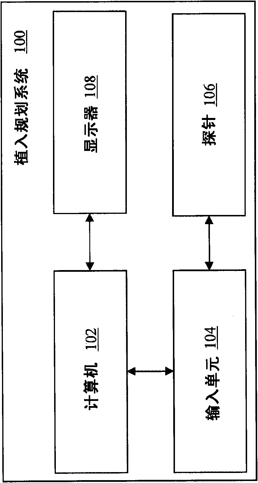
[0045] In an overview, multi-component implant planning is achieved by constraining the adjustment of the individual components of the multi-component implant. Each component is adjustable based on constraints, allowing proper fit of each implant component while preventing improper placement. figure 1 An exemplary multi-component implant planning system 100 according to the present invention is shown. The system includes a computer 102 . ...


PUM


Abstract

Described are computer-based methods and apparatuses, including computer program products, for implant planning for multiple implant components using constraints. A representation of a bone and a representation of a first implant component are displayed with respect to the representation of the bone. A representation of a second implant component is displayed, wherein the first implant component and the second implant component are physically separated and not connected to each other. A positioning of the representation of the second implant component that violates at least one positioning constraint is prevented, wherein the positioning constraint is based on the representation of the first implant component.

Description

technical field [0001] The present invention generally relates to a surgical computer system including a computer program product, and a method for implant planning constrained by multiple implant components, in particular multi-component implants. Background technique [0002] Orthopedic joint replacements may include arthroplasty of the knee, hip, or other joints (eg, shoulder, elbow, wrist, condyles, fingers, etc.). For example, traditional total knee arthroplasty (TKA) involves a long incision, usually in the range of about 6 to 12 inches, to expose the joint for bone preparation and implantation of implant components. The invasive nature of the incisions results in prolonged recovery times for patients. Minimally invasive surgery (MIS) reduces the length of the incision for total knee replacement surgery to a range of approximately 4 to 6 inches. However, smaller incision sizes impair the surgeon's ability to visualize and capture joint anatomy. As a result, the comp...

Claims


Application Information

Patent Timeline
Patent Type & Authority Applications(China)
IPC IPC(8): A61B19/00
CPCA61B2019/5483A61B5/745A61F2002/4632A61B2019/5255A61B5/103A61B5/4528A61F2002/3895A61B5/4514A61F2/3877A61B19/50A61B2019/5437A61B5/4504A61F2/38A61B34/10A61B2034/2055A61B2090/3937A61B2090/3983
Inventor A・贝雷特L・阿拉塔R・圣沃瑞斯J・奥托J・武伊齐克
Owner MAKO SURGICAL CORP
Why Eureka
Try Eureka