Lighting system for three-dimensional printing equipment

A technology of lighting system and support body, applied in the field of lighting system

Active Publication Date: 2011-12-28
NEDERLANDSE ORG VOOR TOEGEPAST-NATUURWETENSCHAPPELIJK ONDERZOEK (TNO)
View PDF5 Cites 10 Cited by
  • Summary
  • Abstract
  • Description
  • Claims
  • Application Information

AI Technical Summary

Problems solved by technology

However, a high numerical aperture may be accompanied by a high sensitivity of the pixel size to the precise LED position

Method used


Image

  • Lighting system for three-dimensional printing equipment
  • Lighting system for three-dimensional printing equipment
  • Lighting system for three-dimensional printing equipment

Examples


Embodiment Construction

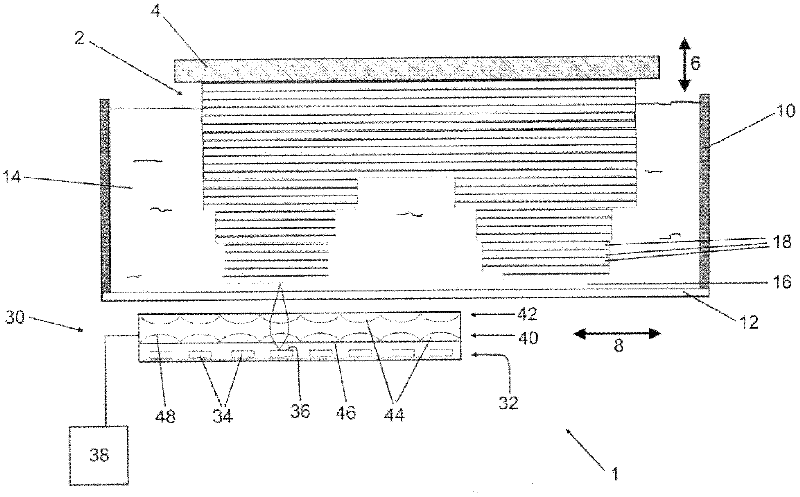
[0045] see first figure 1 , figure 1 is a cutaway side view of an exemplary stereoscopic printing apparatus (SLA) 1 in which the lighting system according to the present invention may be used. This SLA1 can be used to produce a tangible object 2, such as a prototype or model of an article, layer by layer. The SLA1 comprises a carrier plate 4 , a reservoir 10 and a lighting system 30 .

[0046] During production, the tangible object 2 is suspended from a carrier plate 4 on which the first structural layer of the object 2 and indirectly any subsequent layers are glued. The carrier plate 4 is movable in direction 6 by a drive mechanism (not shown) and is moved up by the thickness of one layer each time a new layer is constructed.

[0047] The reservoir 10 contains a liquid photocurable resin 14 . The base plate 12 of the reservoir 10 is optically transparent to light emitted by an illumination system 30, which will be described later. The bottom plate 12 also serves as a s...


PUM


Abstract

The present invention discloses an illumination system (30), comprising: - a plurality of light-emitting diodes (LEDs) (34), each LED having at least a first, light-emitting surface (36) and a second surface (37), at least one of the first and the second surface being substantially flat; - a plurality of electrical pathways (56), selectively connected to the respective LEDs, such that each LED can be individually controlled; and -a levelling surface (46, 52), wherein the levelling surface is substantially flat and in levelling contact with the at least one substantially flat surface (37, 36) of each LED, such that a two-dimensional array of LEDs extends in a plane parallel to the levelling surface.

Description

technical field [0001] The invention relates to the field of three-dimensional printing, in particular to an illumination system for three-dimensional printing equipment. Background technique [0002] Stereo printing, also known as 3D printing, is a rapid prototyping technology used to produce high-precision parts. In simple implementations, 3D printing can use vats of liquid light-curable photosensitive resin and a computer-controlled ultraviolet laser to cure the resin one layer at a time. The construction method is basically cyclic. For each layer corresponding to a piece of the part to be produced, the spots of the laser beam trace individual cross-sectional patterns on the surface of the liquid resin. Laser irradiation cures or solidifies the traced pattern and pastes the pattern to the underlying layer. Once a layer has cured, the part in production—which can rest on a lift platform dipped in the vat of photosensitive resin—can be lowered down a single layer's thick...

Claims


Application Information

Patent Timeline
Patent Type & Authority Applications(China)
IPC IPC(8): B29C67/00B41J2/45
CPCB29C67/007B29C64/129Y10S362/80
Inventor 马克·H·E·维斯H·H·马尔德林克A·J·P·M·弗米尔J·H·T·加玛A·H·J·G·洛门A·李捷佛斯
Owner NEDERLANDSE ORG VOOR TOEGEPAST-NATUURWETENSCHAPPELIJK ONDERZOEK (TNO)
Why Eureka
Try Eureka