
Saw cutting machine for machining decorative strips

A sawing machine and sawing technology, which is applied in the direction of metal sawing equipment, metal processing equipment, sawing machine devices, etc., can solve the problems of simultaneous sawing of decorative strips and flexible adjustment of saw blade cutting direction, etc., so as to avoid processing length The effect of reducing error, reducing mold change and adjustment time, and improving utilization rate

Active Publication Date: 2013-06-19
NINGBO MINTH AUTOMOTIVE PARTS RES&DEV CO LTD
View PDF5 Cites 0 Cited by
  • Summary
  • Abstract
  • Description
  • Claims
  • Application Information

AI Technical Summary

Problems solved by technology

Although the above-mentioned patent can use one sawing machine to cut multiple decorative strips at one time, it is impossible to simultaneously saw both ends of the decorative strips in this patent, and the cutting direction of the saw blade cannot be flexibly adjusted according to different decorative strip structures. To be further improved

Method used


Image

  • Saw cutting machine for machining decorative strips
  • Saw cutting machine for machining decorative strips
  • Saw cutting machine for machining decorative strips

Examples


Embodiment Construction

[0029] The present invention will be further described in detail below in conjunction with the accompanying drawings and embodiments.

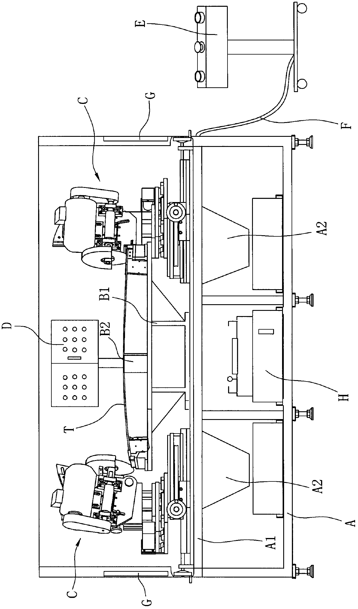
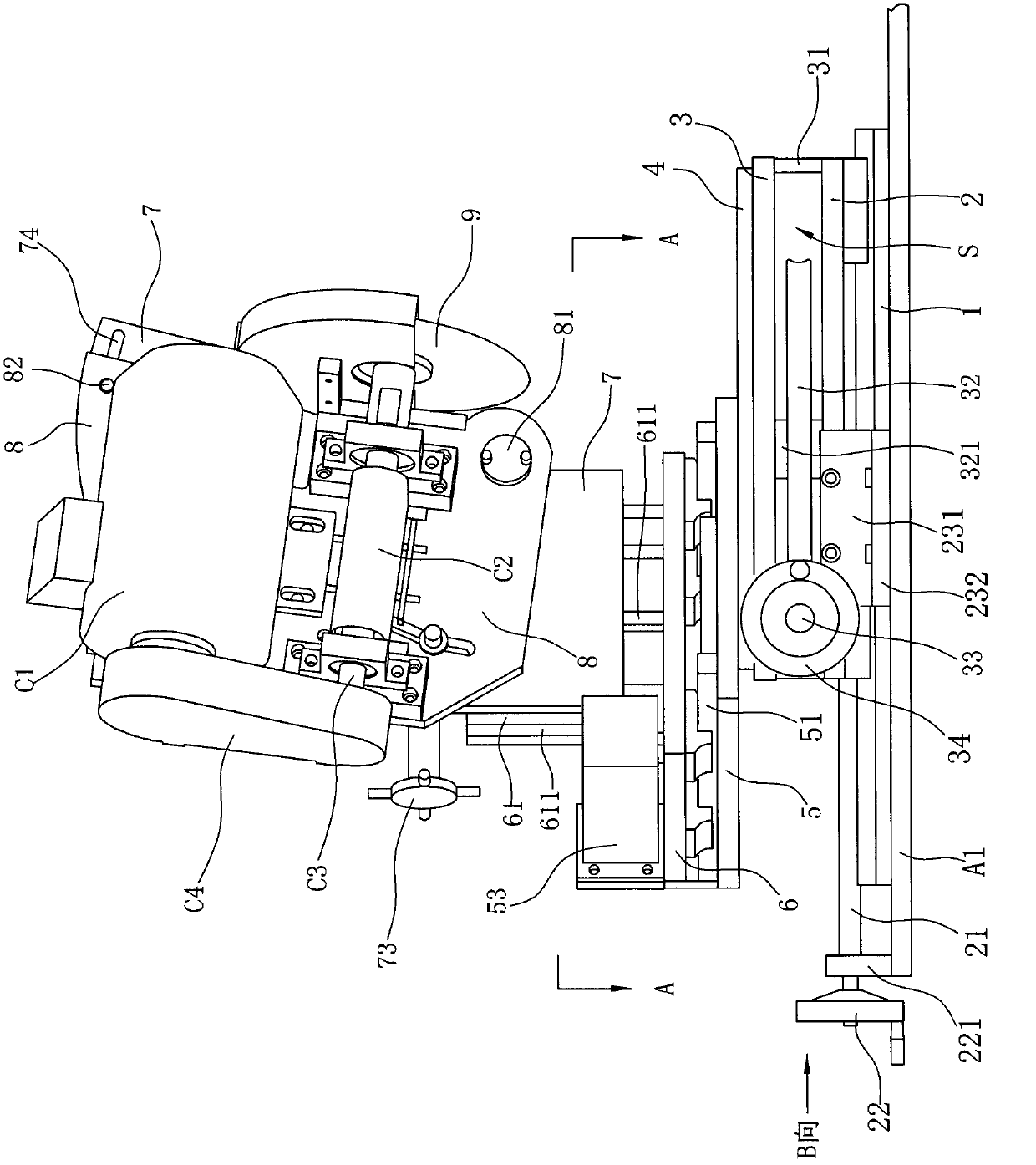
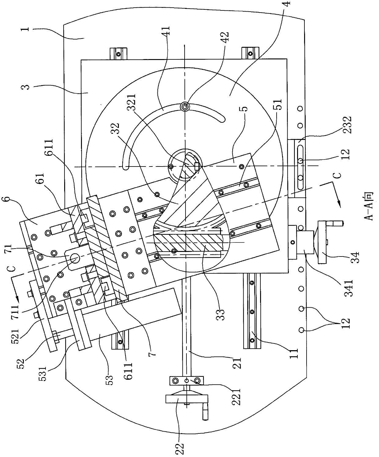
[0030] Such as Figure 1 to Figure 6 As shown, the present embodiment is a sawing machine used for trim strip processing in the automobile industry, and the sawing machine includes

[0031] Frame A, the frame A has a horizontally arranged work surface A1;

[0032] The fixture device is used to clamp the trim strip T to be processed, and the fixture device includes a bracket B1 arranged on the work table A1 of the frame A and a fixture B2 arranged on the bracket B1;

[0033]Two sawing heads C are respectively symmetrically arranged on both sides of the frame A, and the clamp device is arranged between the two sawing heads C, and each sawing head C includes a saw blade 9 and drives the saw. slice 9 rotary cutting power device, and each sawing head C is installed on a driving device that can adjust the three-dimensional cutting angle of the saw...


PUM


Abstract

The invention relates to a saw cutting machine for machining decorative strips. The saw cutting machine comprises a machine frame, saw cutting machine heads and a clamp device, and is characterized in that the two saw cutting machine heads are arranged on two sides of the machine frame; the clamp device is arranged between the two saw cutting machine heads; each saw cutting machine head is arranged on a driving device capable of regulating a three-dimensional cutting angle of saw bit space of the saw cutting machine head; and the driving device is fixedly arranged on the machine frame. In thesaw cutting machine, the saw cutting machine heads are arranged on two sides of the decorative strips, so that two ends of the decorative strips are sawed simultaneously, and the work efficiency is improved; in the process of machining the decorative strips, the two ends of the decorative strips can be sawed only by being clamped once, so the error of machining length due to back-and-forth movement of the decorative strips is avoided, and the accuracy of the machining length of the decorative strips is ensured; and the two saw cutting machine heads can regulate three-dimensional space by the driving device, so that saw bits can regulate the cutting angle flexibly according to the decorative strips with different end part structures, and the time of die change and regulation is shortened.

Description

technical field [0001] The invention relates to a cutting device, in particular to a sawing machine used for processing decorative strips in the automobile industry. Background technique [0002] Automotive decorative strips mainly refer to various automotive exterior accessories such as sealing strips and decorative strips. Most of these decorative strips are slender. During production and processing, they need to be cut to a certain length with sawing equipment as required. In the prior art, the following two structures are usually adopted to realize the cutting process of the decorative strips for vehicles: (1) Using a circular saw machine and attaching four sets of clamps. Method (1) Although this structure is relatively simple, it is impossible to cut both ends of the decorative strip at the same time, and the adjustment is troublesome. Every time the mold is changed, a fixture must be replaced, which is low in efficiency and poor in precision. (2) Fix the two circular...

Claims


Application Information

Patent Timeline
Patent Type & Authority Patents(China)
IPC IPC(8): B23D47/02B23D47/00
Inventor 胡剑英
Owner NINGBO MINTH AUTOMOTIVE PARTS RES&DEV CO LTD
Learn More