Method and device for controlling electrical appliance load
A control method and technology of electrical appliances, which can be applied to electrical devices, transportation and packaging, electric vehicles, etc., and can solve problems such as battery power loss
- Summary
- Abstract
- Description
- Claims
- Application Information
AI Technical Summary
Problems solved by technology
Method used
Image

Examples
Embodiment 1
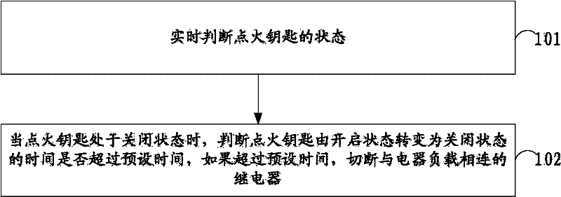
[0036] Embodiment 1 of the present invention proposes a control method for electrical loads, the flow of which is as follows figure 2 As shown, the method includes:
[0037] Step 101, judging the state of the ignition key in real time;
[0038] Step 102: When the ignition key is in the off state, judge whether the time for the ignition key to turn from the on state to the off state exceeds a preset time, and if the time exceeds the preset time, cut off the relay connected to the electrical load.
[0039] The method for reviewing messages provided by the embodiment of the present invention can disconnect the electrical load with the switch not turned off from the battery after the driver turns off the engine and leaves the car, so as to avoid wasting the power resources stored in the battery and avoid Inconveniences such as inability to start the vehicle due to a large amount of power loss in the battery caused by the driver forgetting to turn off the electrical load.
Embodiment 2
[0041] Embodiment 2 of the present invention proposes a control method for electrical loads, which is improved on the basis of Embodiment 1.
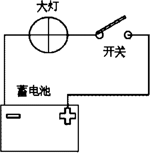
[0042] In this embodiment, a method for controlling an electrical load is described by taking control of a headlight of an automobile as an example.
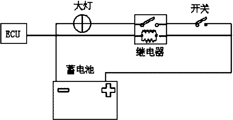
[0043] In this example, if image 3 As shown, by adding relays to the circuit system of the existing car and improving the ECU (Electronic Control Unit, electronic control unit) in the car, the automatic control of the electrical load in the car by the ECU is realized, and the existing problem is solved. In the technology, the car driver forgets to turn off the electrical load in the car, which causes the battery loss problem.
[0044] Wherein, the ECU is the automobile controller of the automobile, and in this embodiment, it is the execution subject of the method for controlling the electrical load in the automobile as follows, for image 3 Control the newly added relay in the car, and...
Embodiment 3
[0059] Embodiment 3 of the present invention proposes a control device for electrical loads, the structure of which is as follows Figure 5 shown, including:
[0060] The ignition key judging module 301 is used to judge the state of the ignition key in real time;
[0061] The time judging module 302 is used to determine whether the time for the ignition key to change from the on state to the off state exceeds the preset time when the real-time judgment module 301 judges that the ignition key is in the off state;
[0062] The closing module 303 is configured to cut off the relay connected to the electrical load when the time judging module 302 judges that the time for the ignition key to change from the on state to the off state exceeds a preset time.
[0063] Further, as Image 6 As shown, the above-mentioned device also includes:
[0064] The timer module 304 is used to start the timer and start timing when the ignition key judging module 301 judges that the ignition key i...
PUM
 Abstract
Description
Claims
Application Information
 - R&D Engineer
- R&D Manager
- IP Professional
- Industry Leading Data Capabilities
- Powerful AI technology
- Patent DNA Extraction
Browse by: Latest US Patents, China's latest patents, Technical Efficacy Thesaurus, Application Domain, Technology Topic.
© 2024 PatSnap. All rights reserved.Legal|Privacy policy|Modern Slavery Act Transparency Statement|Sitemap