
Automatic incubator and working process thereof

An automatic, box-shaped technology, applied in the field of hatching eggs, can solve the problem of difficult temperature control, achieve basic temperature balance, local temperature control is convenient and accurate, and solve the effect of difficult temperature control.

Active Publication Date: 2012-01-11
上海石井畜牧设备有限公司
View PDF6 Cites 3 Cited by
  • Summary
  • Abstract
  • Description
  • Claims
  • Application Information

AI Technical Summary

Problems solved by technology

[0003] Aiming at the problems and defects in the above-mentioned prior art, the object of the present invention is to provide an automatic incubator, which can not only realize the basic balance of temperature in each area of ​​the entire incubator, but also make local temperature control more convenient and accurate, and effectively solve the problem of different It is difficult to control the temperature caused by the heat difference caused by the mixed incubation of week-old embryos and eggs, and it can effectively control the CO in the incubator, especially in the large-scale incubator that accommodates multiple rows of egg racks and mixed incubation of embryos and eggs of different weeks. 2 Concentration, in order to meet the environmental simulation requirements in a large incubator that accommodates multiple rows of egg racks and mixed incubation of embryos and eggs of different weeks

Method used


Image

  • Automatic incubator and working process thereof
  • Automatic incubator and working process thereof
  • Automatic incubator and working process thereof

Examples


Embodiment Construction

[0021] The technical solutions of the present invention will be further described below in conjunction with the accompanying drawings and embodiments.

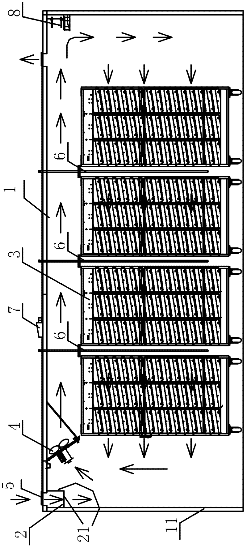
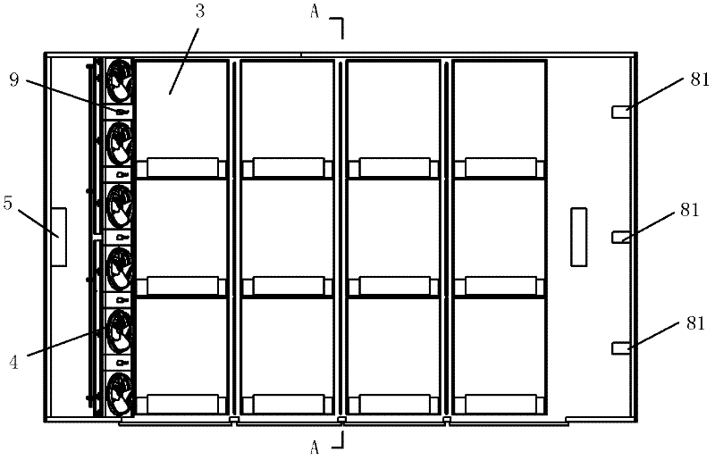
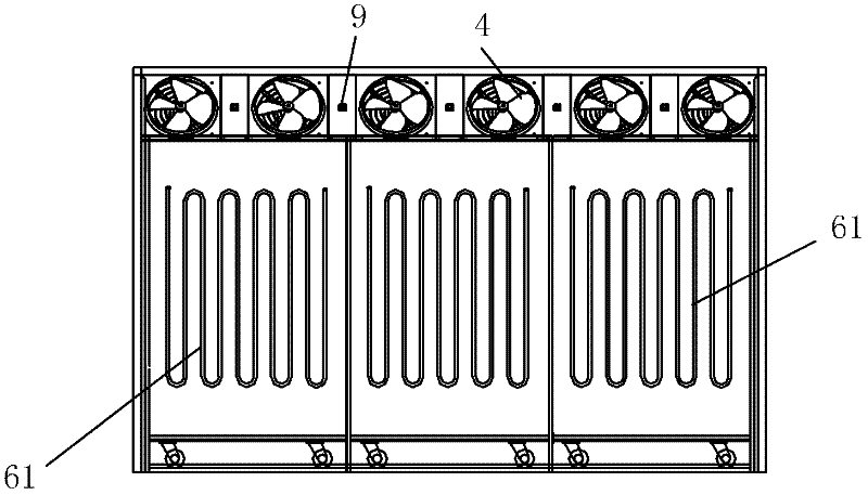
[0022] see figure 1 Shown: a kind of automatic incubator provided by the present invention, comprises: box body 1 and the processor (not shown in the figure) that is located on box body 1, balance air inlet pipe 2, egg rack trolley 3, go to egg rack Vehicle forced air supply fan 4, air inlet 5, heat exchange coil 6, measuring CO in the incubator box 2 Concentration of CO 2 Sensor (not shown in the figure), damper 7 and temperature sensor 8, CO 2 The sensor is set in the box body 1, the damper 7 is set in the middle of the top plate of the box body 1, and the processor is respectively connected with the CO 2 The sensor is connected with the air door 7, and the CO2 concentration exceeds the set value, and the processor controls the opening of the air door 7 through a relay. The processor converts the CO of different days of ...


PUM


Abstract

The invention discloses an automatic incubator and a working process thereof. The incubator comprises a box body, a processor, a balancing air inlet pipe, egg rack carts, a fan, an air inlet, heat exchange coil pipes, a CO2 (carbon dioxide) sensor, an air door and temperature sensors, wherein the CO2 sensor is arranged in the box body; the air door is arranged in the middle of the top plate of the box body; the processor is respectively connected with the CO2 sensor and the air door; the temperature sensors are arranged on a side plate corresponding to a circulating air flue in the box body; the heat exchange coil pipes are arranged between two adjacent rows of the egg rack carts in the box body; the heat exchange coil pipes are provided with joints which are connected with an external hot water source and an external cold water source; the processor is respectively connected with the temperature sensors and the joints; and the processor is used for controlling the communication of the heat exchange coil pipes with the external hot water source or the external cold water source. The working process of the incubator comprises the following steps of: temperature control, humidity control, egg turning on the egg rack carts and CO2 control. The automatic incubator and the working process can enable the simulation of an incubation environment in the incubator to be more precise andthe regulation and control to be simpler and more feasible.

Description

technical field [0001] The invention relates to an automatic hatching machine and its working process, which belongs to the egg hatching technology. Background technique [0002] In the prior art, a balanced air inlet pipe is installed at the air inlet of the incubator, and a fan, a heating pipe and a water cooling pipe are installed on the top plate of the box body. Fresh air enters the body through the balanced air inlet pipe, and the temperature sensor The detection signal controls the heating pipe, the upper water cooling pipe and the lower water cooling coil installed between two adjacent rows of egg rack carts to keep the air temperature within the set temperature range, and then use the fan to force the air to circulate in the box. The circulating air duct makes the temperature in the whole box relatively consistent, and at the same time, the direction of placing the egg rack trolleys is changed so that the width direction of each egg rack trolley is parallel to the w...

Claims


Application Information

Patent Timeline
IPC IPC(8): A01K41/00A01K41/02A01K41/04
Inventor 邹灵孙雪松沈俊锋李玉仁朱辉徐希峰项金辉顾正荣顾韶峰
Owner 上海石井畜牧设备有限公司
Learn More