Eureka AIR delivers breakthrough ideas for toughest innovation challenges, trusted by R&D personnel around the world.

Non-directional radio telephone receiver

A wireless telephone, non-directional technology, applied in the direction of telephone structure, electrical components, transducer circuits, etc., can solve problems such as inability to use left and right hands, damage to the earpiece, and inability to transmit sound

Inactive Publication Date: 2012-01-11
FUJIAN STAR NET WISDOM TECH CO LTD
View PDF4 Cites 13 Cited by
  • Summary
  • Abstract
  • Description
  • Claims
  • Application Information

AI Technical Summary

Problems solved by technology

[0003] (1) Considering that it is convenient to take the handset no matter on the left or right side of the body, most of the telephone handsets are now placed vertically. Pick up the handset, which is not ergonomic;
[0004] (2) Based on the above factors, there are currently a small number of handsets that are placed horizontally, but due to the different outlet positions of the handset crystal head, this placement method cannot be used for both left and right hands;
[0005] (3) As for the wireless handset, the internal microphone and speaker are separated and have obvious directionality, that is, the speaker and microphone cannot be used upside down, otherwise you will not be able to hear the sound, and you will not be able to transmit the sound to the other party ;
[0006] (4) In addition, most portable handset chargers use DC charging, and the direction of the positive and negative poles must not be reversed, otherwise the handset will be damaged, which also enhances the inconvenience of using the phone handset
[0007] Based on the above analysis, the existing telephone handsets cannot meet the requirements of ease of use and need to be improved

Method used


Image

  • Non-directional radio telephone receiver
  • Non-directional radio telephone receiver
  • Non-directional radio telephone receiver

Examples


Embodiment Construction

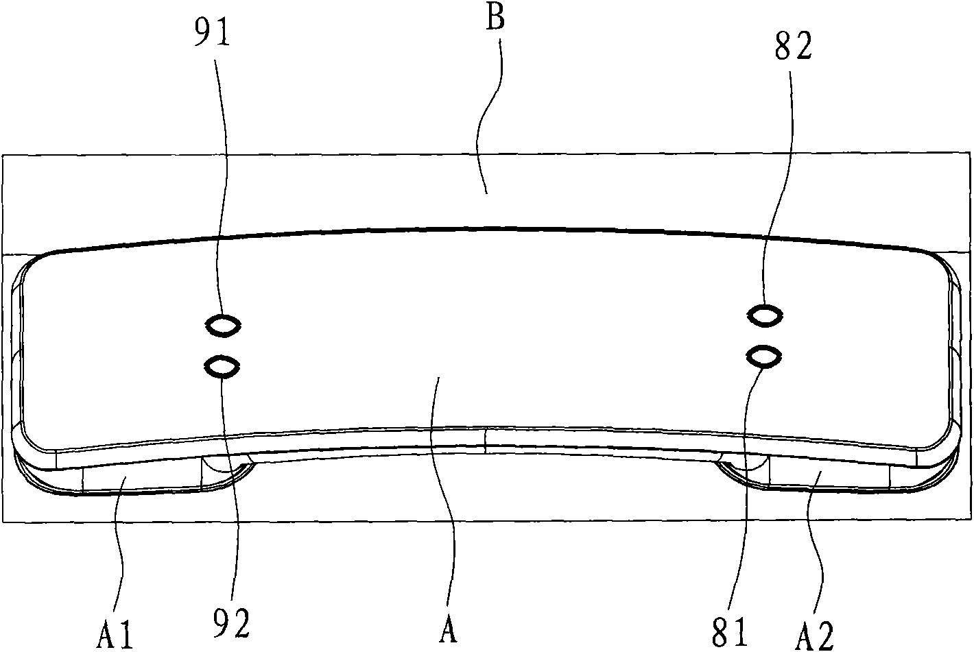
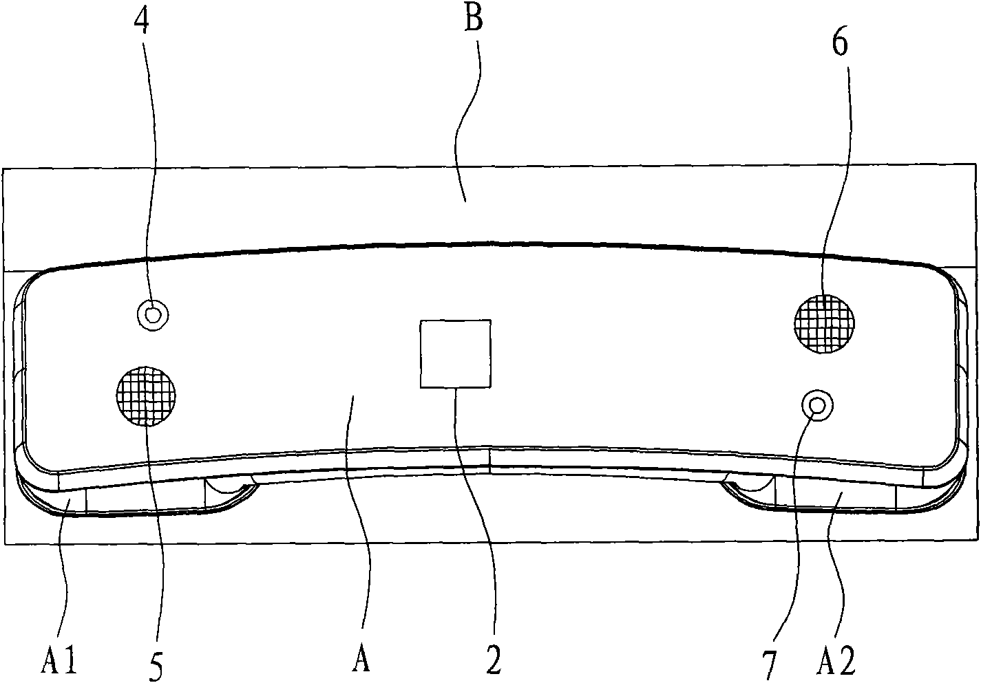
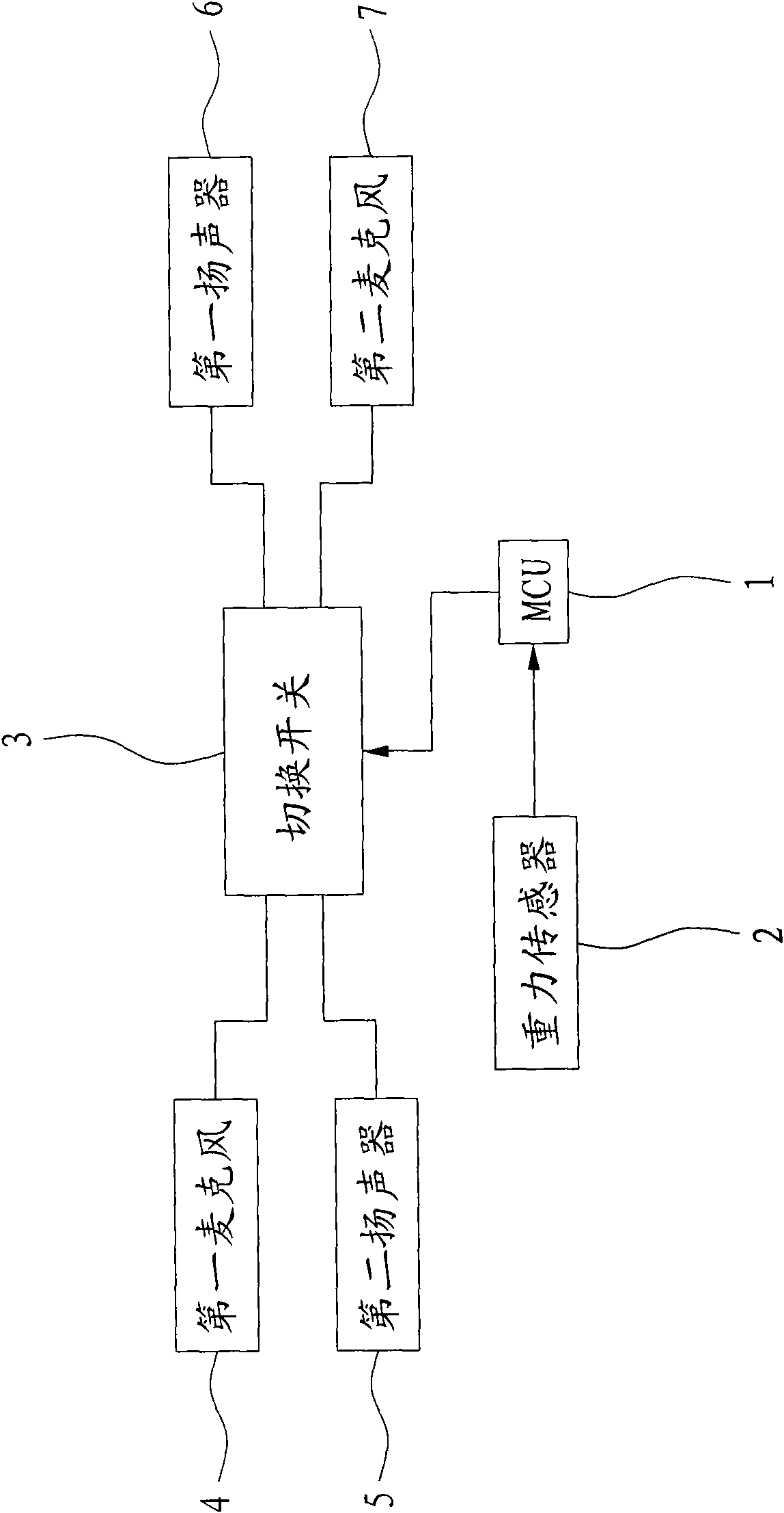
[0027] reference Figure 1 to Figure 3 As shown, the present invention provides a non-directional wireless telephone receiver A, including MCU 1, gravity sensor 2, switch 3, first microphone 4, second microphone 5, first speaker 6 and second speaker 7, respectively Introduction.

[0028] The gravity sensor 2 adopts a three-axis gravity acceleration sensor, which is set in the telephone receiver A and is electrically connected to the MCU 1. The posture data of the telephone receiver A can be collected when the receiver A is picked up and sent to the MCU 1.

[0029] The first microphone 4 and the first speaker 6 are connected through the switch 3, and the two are separately arranged at the two ends of the earpiece A. When the circuits of the two are connected, the telephone conversation can be completed.

[0030] The second microphone 7 and the second speaker 5 are also connected through the switch 3, and they are separately arranged at both ends of the earpiece A, and the positional ...


PUM


Abstract

The invention discloses a non-directional radio telephone receiver which comprises an MCU (Microprogrammed Control Unit), a gravity sensor, a selector switch, a first microphone, a second microphone, a first speaker and a second speaker, wherein the gravity sensor is connected with the MCU, and used for sending sensing data to the MCU; the selector switch is connected with the MCU, and is used for connecting a communication line of the first microphone and the first speaker under the control of the MCU or connecting a communication line of the second microphone and the second speaker; and the first microphone and the first speaker are respectively arranged at two ends of the receiver, the second microphone and the second speaker are respectively arranged at two ends of the receiver, the first microphone and the second microphone are positioned at opposite sides of the receiver, and the first speaker and the second speaker are positioned at opposite sides of the receiver. The non-directional radio telephone receiver accords with the human engineering principle, and can realize a communication function in two directions.

Description

Technical field [0001] The invention relates to a telephone receiver, in particular to a radio receiver structure. Background technique [0002] The appearance of the telephone has greatly facilitated the communication between people. At present, the telephone receiver used in the building intercom system has the following characteristics: [0003] (1) Considering that the handset is easy to access regardless of the body's left and right sides, most of the telephone handsets are now placed vertically. This structure makes it possible to turn the wrist when accessing, regardless of whether the handset is placed on the left or right. The earpiece is not ergonomic; [0004] (2) Based on the above factors, there are currently a few handsets that are placed horizontally, but due to the different outlet positions of the handset crystal head, this placement method cannot be used for both left and right hands; [0005] (3) As for the wireless earpiece, the internal microphone and speaker are...

Claims


Application Information

Patent Timeline
IPC IPC(8): H04M1/03H04R3/00
Inventor 林海林鸿程
Owner FUJIAN STAR NET WISDOM TECH CO LTD
Why Eureka
Eureka Blog
Learn More