Wiper blade having an adapter unit for attaching to a wiper arm

A transfer unit and wiper blade technology, which is applied to vehicle cleaning, vehicle maintenance, transportation and packaging, etc., can solve the problems of complexity, time-consuming wiper blade assembly, and difficulty in manually operating the transfer unit, and achieves a simple structure, cost-effective effect

Active Publication Date: 2012-01-11
ROBERT BOSCH GMBH
View PDF7 Cites 9 Cited by
  • Summary
  • Abstract
  • Description
  • Claims
  • Application Information

AI Technical Summary

Problems solved by technology

A disadvantage of the prior art is that a combination of different movement sequences is required for fastening the adapter unit on the basic connection of the wiper blade, that is to say, first passing through at a predetermined angle, then performing a swivel movement and finally using the Performs roughly linear motion under predetermined pressure
Manual actuation of the adapter unit is therefore difficult and assembly of the wiper blade is laborious and complicated

Method used


Image

  • Wiper blade having an adapter unit for attaching to a wiper arm
  • Wiper blade having an adapter unit for attaching to a wiper arm
  • Wiper blade having an adapter unit for attaching to a wiper arm

Examples


Embodiment approach

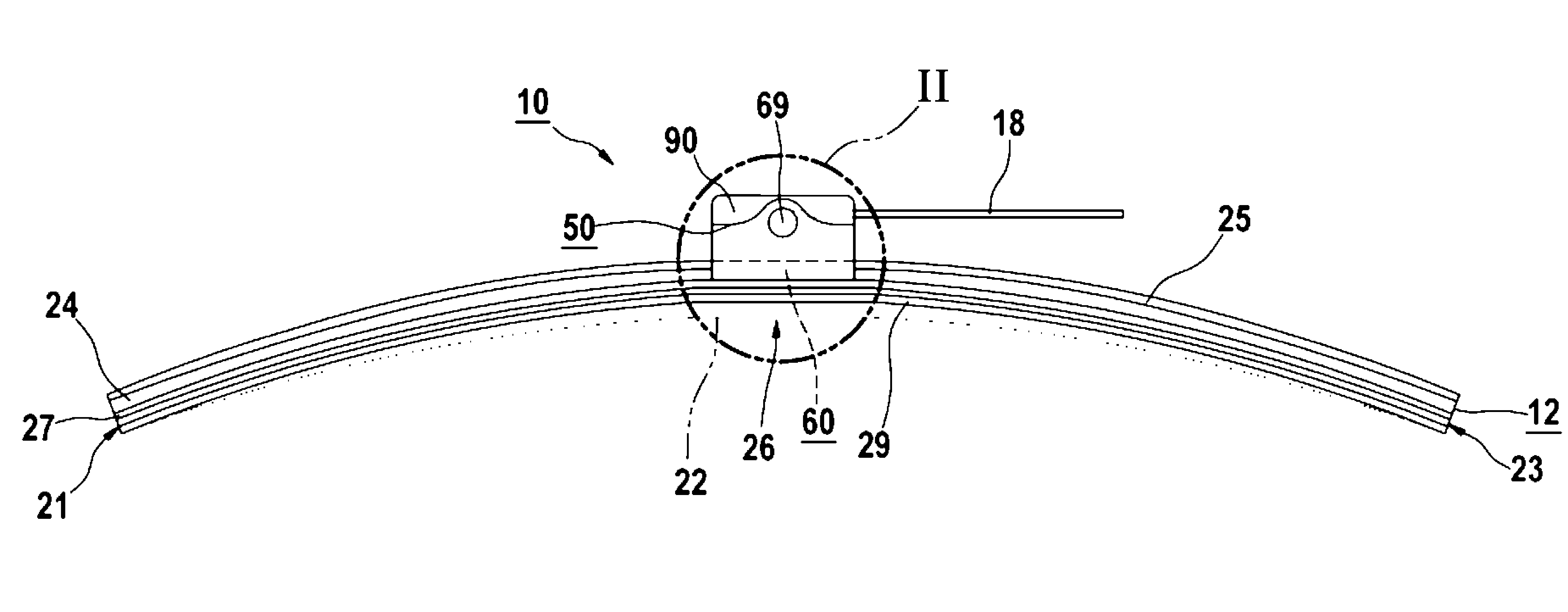
[0028] According to one embodiment, the wiper blade 10 is designed as a flat beam, ie the wiper strip 12 has a lateral longitudinal groove in which two bearings are arranged. Guide rails, preferably spring guide rails. Alternatively, the wiper strip 12 can be designed as a hollow profile with an approximately central longitudinal channel in which a separate support rail is arranged. The wiper strip 12 and the base connecting device 60 arranged thereon are preferably configured in a hingeless manner, wherein the base connecting device 60 is preferably preassembled on the wiper strip 12 .

[0029] exist figure 1 The wiper blade 10 is not completely placed on the glass 22, only its axial wiper blade ends 21, 23 are close to the glass 22, and the wiper slat 12 is in the middle of the wiper blade 26 , that is to say approximately in the region of the adapter unit 50 is still at a distance from the glass 22 . The wiper strip 12 bears against the windshield 22 when a predetermined...


PUM


Abstract

The invention relates to a wiper blade (10) for a windshield wiper, having a wiper strip (12) and an adapter unit (50) for attaching the wiper strip (12) to a wiper arm, wherein the adapter unit (50) is attached at a base connection device (60) provided on the wiper strip (12), wherein the adapter unit (50) comprises a first adapter holder (52) and a second adapter holder (58) mounted on the base connection device (60) at a distance from each other, and catch elements (51, 59) facing each other, on which a connection element (55) associated with the adapter unit (50) is engaged for connecting with the wiper arm.

Description

technical field [0001] The invention relates to a wiper blade for a wiper with a wiper strip and an adapter unit for fastening the wiper strip to a wiper arm, wherein the adapter unit is fastened to a Set on the base connection on the wiper slat. Background technique [0002] Document WO 2008 / 145481 A1 describes such a wiper blade with a wiper strip on which a basic connecting device that can be connected to an adapter unit is provided. The adapter unit is fixed on the basic connection device through a snap connection. For this purpose, the adapter unit has two snap pins with widened, rounded ends and the basic connection device has two associated snap brackets with elastic support arms, of which two The two support arms respectively use arc-shaped protrusions to buckle the bracket. During fastening of the adapter unit on the base connection device, the adapter unit first passes with its front axial end area at a predetermined angle on the base connection device and then ...

Claims


Application Information

Patent Timeline
Patent Type & Authority Applications(China)
IPC IPC(8): B60S1/40B60S1/38
CPCB60S1/387B60S1/40B60S1/4067B60S1/3863B60S1/3806B60S1/3874
Inventor H.德庞特
Owner ROBERT BOSCH GMBH
Why Eureka
Try Eureka