Transmitter fault diagnosis circuit and method thereof

A fault diagnosis and transmitter technology, which is applied in the direction of instruments, special recording/indicating devices, measuring devices, etc., can solve the problems of time-consuming and manpower, troublesome inspection and maintenance, and no output signal, etc. Effect of falling dust and prolonging service life

Inactive Publication Date: 2012-01-18
SANY HEAVY IND CO LTD (CN)
View PDF5 Cites 16 Cited by
  • Summary
  • Abstract
  • Description
  • Claims
  • Application Information

AI Technical Summary

Problems solved by technology

[0003] Nowadays, pressure transmitters are used more and more. In actual work, due to the influence of various environmental factors, pressure transmitters will be damaged or malfunction, resulting in no output or abnormal signals.
Under normal circumstances, it is difficult to determine the specific damaged part when the pressure transmitter is broken. The damaged part may be the sensor core or the transmitter processing module. It is difficult to quickly locate the fault. Now many manufacturers are dealing with the failed pressure transmitter. It is customary to dismantle the pressure transmitter when using the transmitter, and check it according to the conventional method, which is troublesome to check and repair, and consumes time and manpower

Method used


Image

  • Transmitter fault diagnosis circuit and method thereof
  • Transmitter fault diagnosis circuit and method thereof
  • Transmitter fault diagnosis circuit and method thereof

Examples


Embodiment Construction

[0028] The following will clearly and completely describe the technical solutions in the embodiments of the present invention with reference to the accompanying drawings in the embodiments of the present invention. Obviously, the described embodiments are only some, not all, embodiments of the present invention. Based on the embodiments of the present invention, all other embodiments obtained by persons of ordinary skill in the art without creative efforts fall within the protection scope of the present invention.

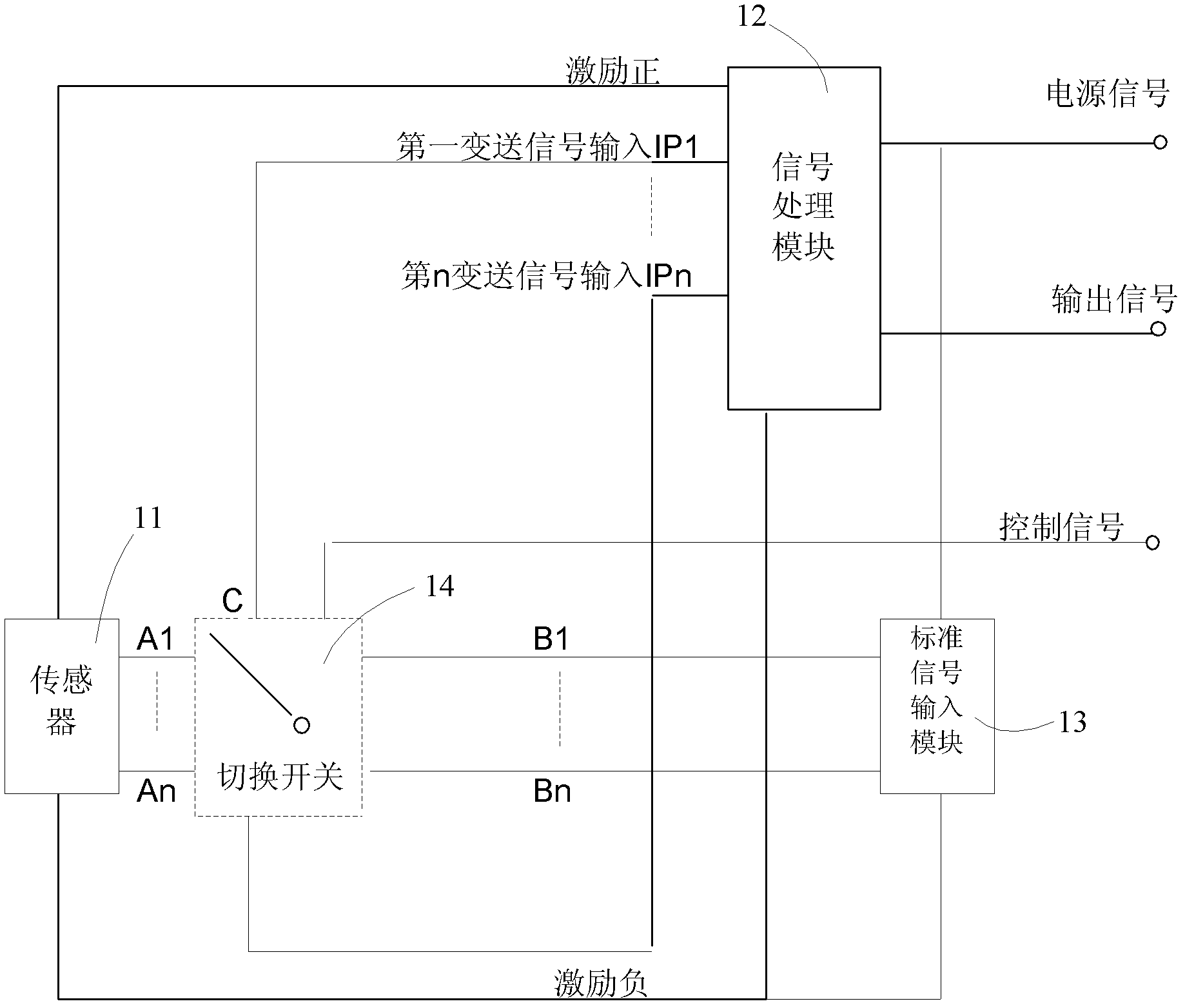
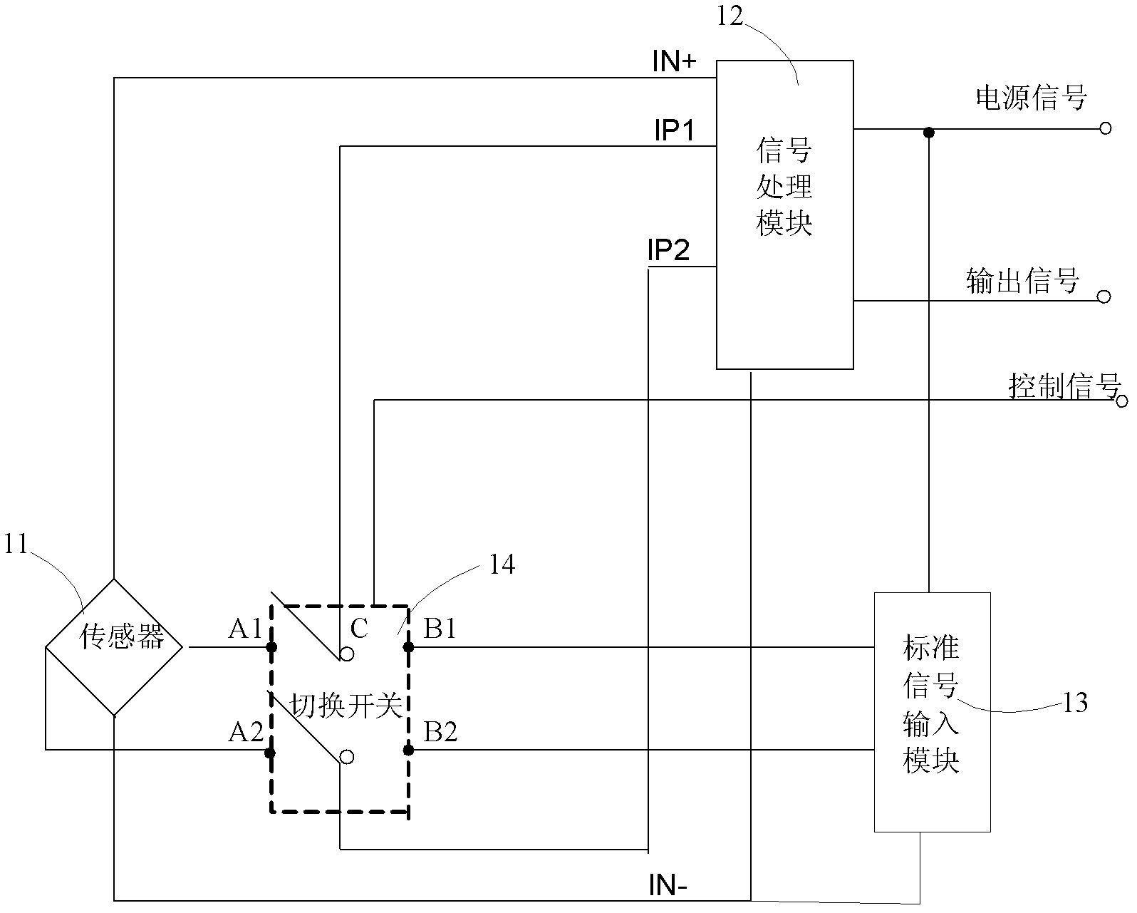
[0029] Such as figure 1 As shown, the present invention provides a transmitter fault diagnosis circuit, including:

[0030] The sensor 11 is used to detect a physical quantity and form a detection signal; the detected physical quantity may be parameter information such as temperature, pressure, liquid level, and flow.

[0031] The signal processing module 12 is used to receive the detection signal of the sensor and output it after processing; the processing of the...


PUM


Abstract

The invention relates to a transmitter fault diagnosis circuit and a method thereof. The fault diagnosis circuit comprises a sensor, a signal processing module, a standard signal input module, and a change over switch. The change over switch connects with the sensor and the signal processing module, and connects with the standard signal input module and the signal processing module simultaneously. According to the invention, a standard signal is inputted to the signal processing module through the standard signal input module, and connection between the sensor and the signal processing module or connection between the standard signal input unit and the signal processing module is switched through the change over switch. When a fault appears, the change over switch disconnects the connection between the sensor and the signal processing module, and connects the standard signal input module with the signal processing module, the standard signal is inputted to the signal processing module through the standard signal input module, according to the standard signal, the signal processing module carries out processing, followed by outputting, if an output result is normal, the sensor has a fault. Conversely, the signal processing module has a fault. The transmitter fault diagnosis circuit has the characteristics of simple structure, low cost and convenient maintenance.

Description

technical field [0001] The invention relates to a fault diagnosis circuit of a transmitter. In addition, the invention also relates to a fault diagnosis method of a transmitter. Background technique [0002] Sensors play an irreplaceable role in scientific research and technology development, especially in information technology, automation technology, modern manufacturing and other technologies. Pressure sensors are currently the most widely used sensors and are widely used in petroleum, chemical, etc. Industrial fields and national defense fields such as aviation and aerospace. [0003] Nowadays, pressure transmitters are used more and more. In actual work, due to the influence of various environmental factors, pressure transmitters will be damaged or malfunction, resulting in no output or abnormal signals. Under normal circumstances, it is difficult to determine the specific damaged part when the pressure transmitter is broken. The damaged part may be the sensor core or ...

Claims


Application Information

Patent Timeline
Patent Type & Authority Applications(China)
IPC IPC(8): G01D18/00G01L27/00G01L25/00
CPCG01L27/007G01D3/10
Inventor 周翔王汉其袁庆国
Owner SANY HEAVY IND CO LTD (CN)
Why Eureka
Try Eureka