
Sand collector

A technology for collecting sand and a set, which is applied to measuring devices, instruments, etc., can solve the problems of incapable of layered sand collecting structure, unadjustable sand collecting height, and complexity, etc., and achieves adjustable sand collecting height, low manufacturing cost, and sand extraction. handy effect

Inactive Publication Date: 2013-01-23
NORTHEAST INST OF GEOGRAPHY & AGRIECOLOGY C A S
View PDF7 Cites 0 Cited by
  • Summary
  • Abstract
  • Description
  • Claims
  • Application Information

AI Technical Summary

Problems solved by technology

[0003] The purpose of the present invention is to solve the problems of non-adjustable sand collection height, layered sand collection and complicated structure of the existing sand collection device, and further provide a sand collection device

Method used


Image

  • Sand collector
  • Sand collector
  • Sand collector

Examples


specific Embodiment approach 1

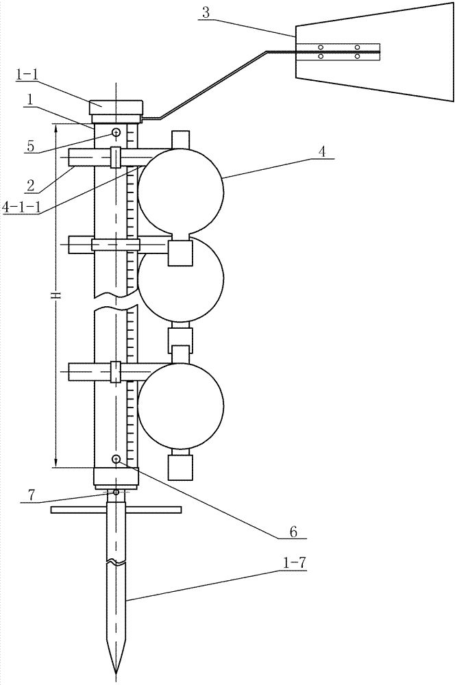
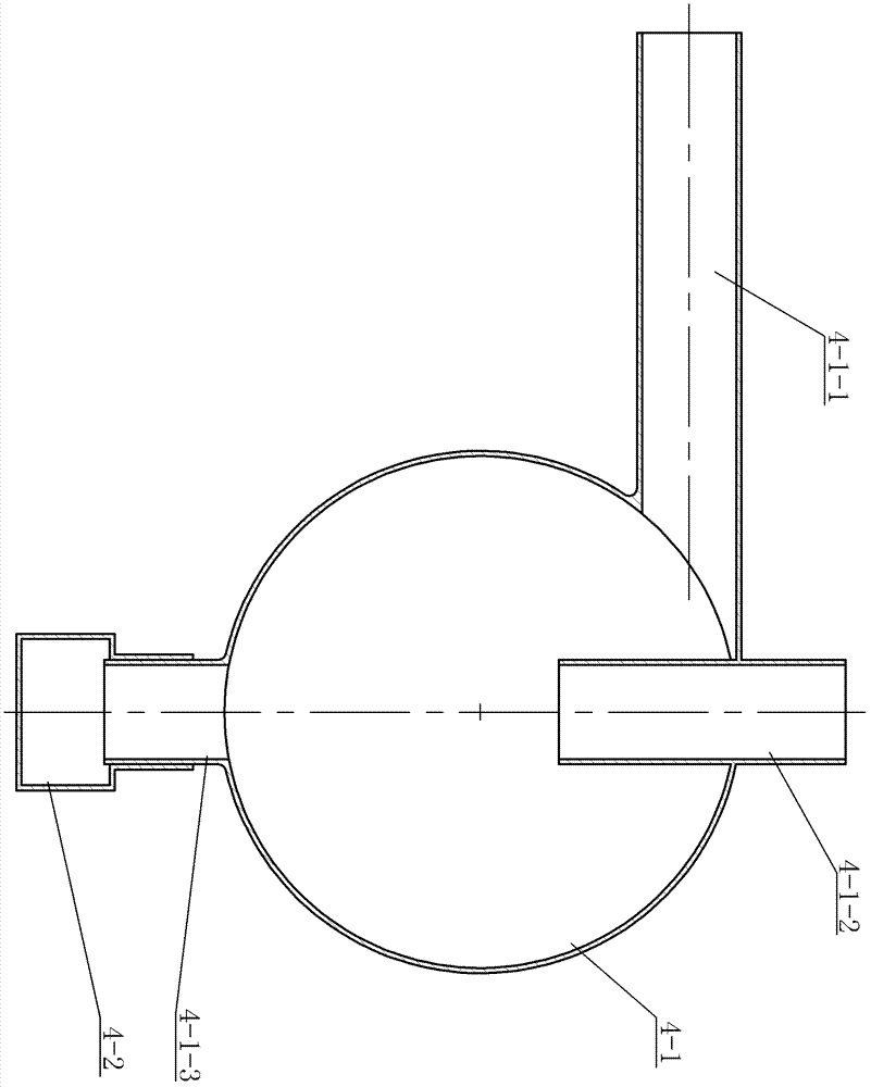
[0007] Specific implementation mode one: combine Figure 1 to Figure 5 Describe this embodiment, a kind of sand collecting device of this embodiment comprises wind rudder 3, rotator 1, pole 1-7, multiple sets of fixers 2 and multiple sand collectors 4, described wind rudder 3 Including a fixed ring 3-1, a connecting curved rod 3-2 and a rudder plate 3-3, the rotator 1 includes an inner cylinder 1-5, an outer cylinder 1-4, a shield 1-1, and an annular gasket 1-6. Two bearing bushes and two bearings. Each sand collector 4 includes a deceleration hall 4-1 and a sand collection box 4-2. The middle part of the upper end of the deceleration hall 4-1 is provided with an air outlet pipe 4- 1-2, the air outlet pipe 4-1-2 is vertically arranged, and a sand inlet pipe 4-1-1 perpendicular to the axis of the air outlet pipe 4-1-2 is provided on the side wall of the deceleration hall 4-1, The middle part of the lower end of the deceleration hall 4-1 is provided with a sand outlet pipe 4-1-...

specific Embodiment approach 2

[0009] Specific implementation mode two: combination image 3 To illustrate this embodiment, the device of this embodiment also includes a first jacking wire 5, and the upper end of the outer cylinder 1-4 is sleeved in the upper bearing bush 1-3-1 and passed through the first jacking wire 5 with the upper bearing bush 1-3-1. Fixed connection. With such arrangement, it is easy to disassemble and meet the design requirements. Others are the same as in the first embodiment.

specific Embodiment approach 3

[0010] Specific implementation mode three: combination image 3 Describe this embodiment, the device of this embodiment also includes a second jacking wire 6, the lower end of the outer cylinder 1-4 is set in the lower bearing bush 1-3-2 and fixed with the lower bearing bush 1-3-2 through the second jacking wire 6 connect. With such arrangement, it is easy to disassemble and meet the design requirements. Others are the same as in the first or second embodiment.


PUM


Abstract

The invention discloses a sand collector, in particular relates to a sand collecting device, solving the problems of incapability of regulating sand collecting height and collecting sand by layers in the traditional sand collector. The sand collecting device comprises a wind rudder, a rotator, an upright, a plurality of fixer and a plurality of sand collectors, wherein the wind rudder comprises afixing ring, a connecting cranked lever and a rudder plate; the rotator comprises an inner cylinder, an outer cylinder, a shield, two shaft bushes and two bearings; and each sand collector comprises a speed reduction box and a sand collection box, the middle of the upper end of the speed reduction box is provided with an air outlet pipe which is vertically arranged, a sand inlet pipe vertical to the axial line of the air outlet pipe is arranged on the side wall surface of the speed reduction box, the middle of the lower end of the speed reduction box is provided with a sand outlet pipe coincident with the axial line of the air outlet pipe, the outlet end of the sand outlet pipe is connected with the sand collection box in a sealing manner, the inner cylinder is sleeved in the outer cylinder and is rotatably connected with the outer cylinder through the upper bearing arranged in the upper shaft bush and the lower bearing arranged in the lower shaft bush, and the fixed ring is detachably connected with the connection cranked lever.

Description

technical field [0001] The invention relates to a dust collecting device. Background technique [0002] my country has a vast territory and many types of soil. There are also large areas of wind-sand soil or wind-erosive soil. Wind-sand is a great hazard to the ecological environment. Sand-collecting devices are important tools for evaluating the intensity of soil wind-sand occurrence and the effect of soil conservation and sand control. At present, although there are many kinds of dust collection devices used to evaluate the soil conservation effect of conservation tillage, their practicability and sand collection effect are poor. It is inconvenient to take sand after sand collection, and the work reliability is poor. Contents of the invention [0003] The object of the present invention is to provide a sand collection device to solve the problems of non-adjustable sand collection height, layered sand collection and complicated structure of the existing sand collection d...

Claims


Application Information

Patent Timeline
Patent Type & Authority Patents(China)
IPC IPC(8): G01D21/02
Inventor 王其存刘宝江刘慧涛杨帆
Owner NORTHEAST INST OF GEOGRAPHY & AGRIECOLOGY C A S
Learn More