Data output/input method with application of image index structure

An image index, output and input technology, applied in the field of image recognition, can solve the problems of difficult distinction, increase printing difficulty, high density of micro-image units, etc., and achieve the effect of good visual effect

Active Publication Date: 2012-01-18
SONIX TECH
View PDF2 Cites 7 Cited by
  • Summary
  • Abstract
  • Description
  • Claims
  • Application Information

AI Technical Summary

Problems solved by technology

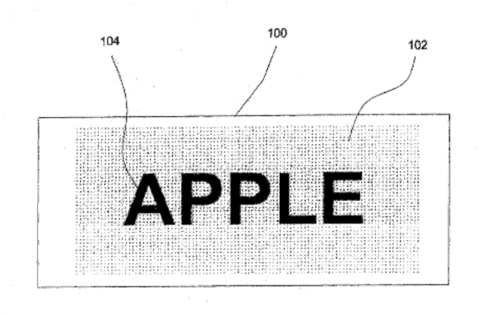
[0006] like figure 1 As shown, the image index 102 usually coexists with the main information 104 on the object surface 100; therefore, when the density of the micro-image unit is higher, the visual effect is worse, and the human eye is more likely to perceive the existence of the image index 102 and make the image index 102 Increased chance of confusion with main message 104
On the other hand, when the image index 102 is formed in a limited object surface area, under the premise of providing the same amount of information, the excessively high distribution density of micro-image units will cause the distance between two adjacent micro-image units to be too small; therefore , when the micro-image units are formed on the paper by, for example, printing, it will cause more obvious visual disturbance
If this visual interference is to be reduced, it is usually necessary to further reduce the size of the micro-image unit, which will increase the resolution requirements of the printing press and paper, and it is also easy to miss dots during printing, which relatively increases the difficulty of printing and is likely to cause damage to the optical device. Misinterpreted or difficult to distinguish
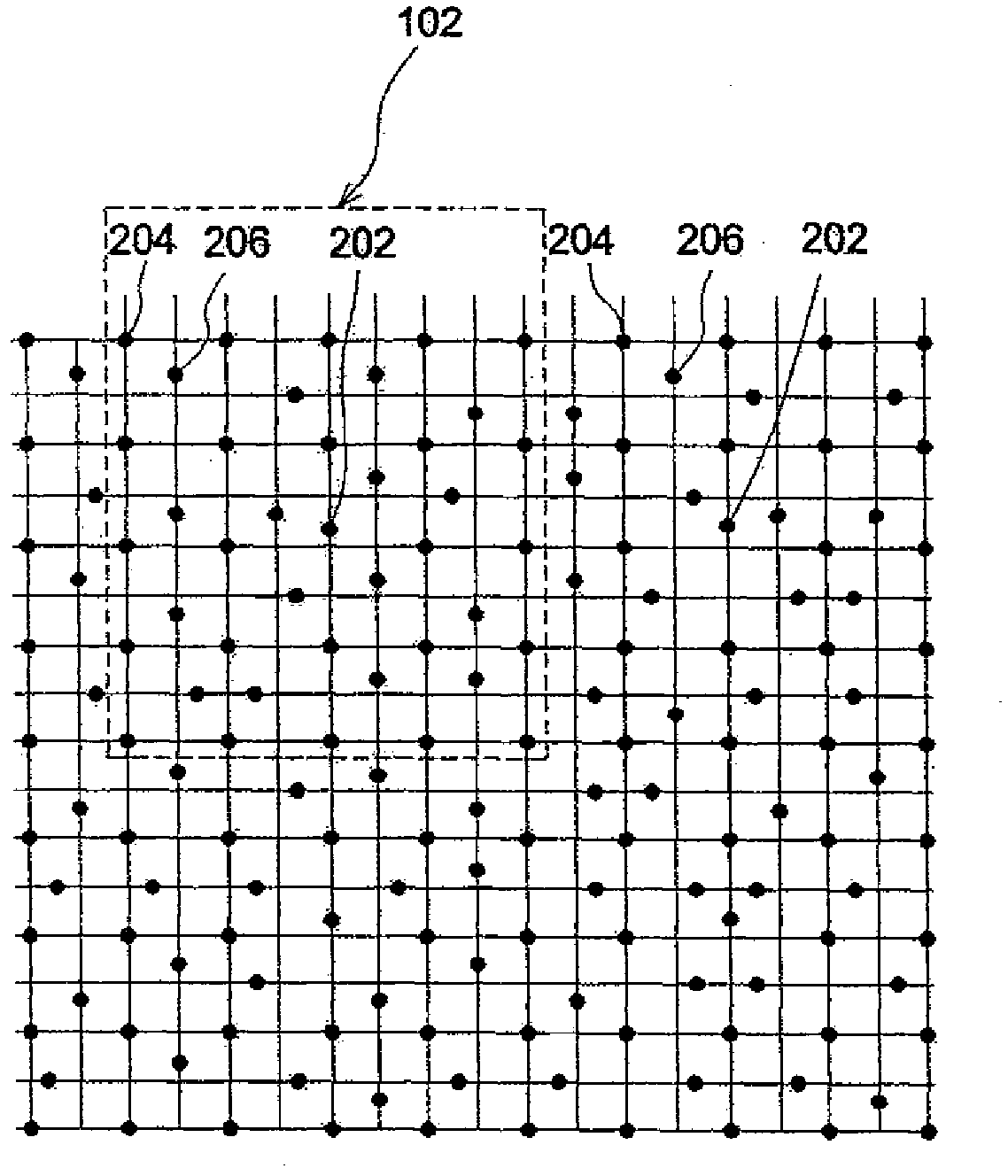
image 3 The design of the existing image index 102 shown clearly leads to an excessively high density of micro-image units, thereby causing the above-mentioned various problems

Method used


Image

  • Data output/input method with application of image index structure
  • Data output/input method with application of image index structure
  • Data output/input method with application of image index structure

Examples


Embodiment Construction

[0036] Figure 4 A schematic diagram of a pattern formed by arranging a plurality of image indicators 10 designed for an embodiment of the present invention, Figure 5 It is an enlarged schematic diagram of one of the image indicators 10 to clearly illustrate the design of the present invention. Such as Figure 5 As shown, the image pointer 10 includes a content data part 12 and a header 14 . According to this embodiment, the content data portion 12 includes 9 micro-image units composed of 9 dots 16; and the area occupied by the content data portion 12 is divided into 9 state areas 18, thereby forming a 3×3 plane Dimensional status area array such that each status area 18 includes a dot 16. According to the design of this embodiment, different placement positions of a dot 16 in a status area 18 can be used to represent a value in the corresponding index data. Specifically, if Figure 6 As shown, a state area 18 can be equally divided into four virtual areas, and dots 16 a...


PUM


Abstract

The invention provides a data output/input method with application of an image index structure. The data output/input method comprises the steps of: forming at least one image index structure corresponding an index datum on an object surface, wherein the image index structure comprises a content data part and a header part, the content data part comprises a plurality of micro image units, a region occupied by the content data part is divided into a plurality of state regions, each state region is provided with one micro image unit, the micro image unit is optionally located in one of a plurality of virtual regions formed by uniformly dividing the state region, the header part comprises a plurality of micro image units which are arrayed in a preset manner so as to provide header information for recognizing an image index; and optically reading the object surface so as to obtain an amplified image containing the image index structure to further capture the index data corresponding to the image index structure.

Description

[0001] This application is a divisional application of the patent application titled "Image Index Structure" filed on April 26, 2006 with the application number "200610075770.8". technical field [0002] The invention relates to image recognition (pattern / image recognition) technology, specifically a data output and input method using an image index structure. Background technique [0003] figure 1 It is a schematic diagram of a graphical indicator 102 formed on a surface 100 of an object. Such as figure 1 As shown, the image indicator 102 is composed of many micro image units. Since the micro image unit is quite small, it is easy to be ignored visually, or interpreted as the background color by human eyes. Image index 102 and main information (main information) 104 (such as figure 1 The character pattern "APPLE") is jointly formed on the surface 100 of an object such as paper by means of, for example, printing. The image index 102 corresponds to an index data, and does...

Claims


Application Information

Patent Timeline
Patent Type & Authority Applications(China)
IPC IPC(8): G06K9/62
Inventor 蔡曜鸿陈丽卿
Owner SONIX TECH
Why Eureka
Try Eureka