Yarn winding device
A winding device and yarn technology, which is applied in the directions of transportation and packaging, delivery of filamentous materials, thin material processing, etc., can solve the problems of costing the operator's energy and the winding angle of the package cannot reach the winding angle, etc. Achieve the effect of avoiding mistakes in setting operations
- Summary
- Abstract
- Description
- Claims
- Application Information
AI Technical Summary
Problems solved by technology
Method used
Image

Examples
Embodiment 1
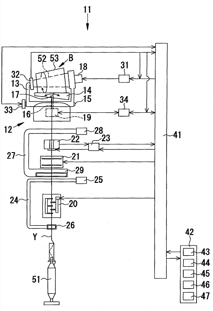
[0029] use Figure 1 to Figure 5 The yarn winding device 11 according to the first embodiment of the present invention will be described.
[0030] The yarn winding device 11 in this embodiment generates the package 53 in a manner of combining step precision control and creep control. Such as figure 1 As shown, the yarn winding device 11 winds the yarn Y around the winding tube 52 to form a yarn layer while traversing the yarn Y on the yarn supplying bobbin 51 by the traversing device 12, thereby A tapered package 53 is produced. in addition, figure 1 One yarn winding device is shown, and an automatic winder is constituted by arranging a plurality of such yarn winding devices 11 in parallel.
[0031] In this specification, the winding tube 52 and the package 53 are collectively referred to as a winding bobbin B. As shown in FIG. That is, the winding bobbin B on which the yarn layer is not formed is the winding tube 52 , and the winding bobbin B on which the yarn layer is f...
Embodiment 2
[0063] use attached Figure 6 The yarn winding device 11 according to the second embodiment of the present invention will be described. The yarn winding device 11 according to this embodiment generates the package 53 by combining step precision control and creep control. However, in the yarn winding device 11 of the second embodiment, the major difference from the first embodiment is that the traverse width becomes narrower than the set traverse width by creep control. , the driving of the winding bobbin drive motor 18 is controlled such that the peripheral speed of the winding bobbin B is temporarily increased. Since other configurations and controls are the same as those of Embodiment 1, detailed description thereof will be omitted.
[0064] Figure 6 It is a graph showing the relationship between the traverse speed and the peripheral speed of the winding bobbin B in this embodiment, showing the relationship between the control of the winding bobbin drive motor 18 and the...
Embodiment 3
[0069] use Figure 7 The yarn winding device 11 according to the third embodiment of the present invention will be described. In the yarn winding device 11 according to this embodiment, when the traverse width is narrower than the set traverse width by creep control, the peripheral speed of the winding bobbin B and the traverse guide The traverse speed of the yarn device 17 is controlled so that the traveling speed of the yarn Y wound on the winding bobbin B is the same as the traveling speed of the yarn Y before the traverse width of the traverse guide 17 is reduced. . Since other configurations and controls of the yarn winding device 11 of the third embodiment are the same as those of the first embodiment, detailed description thereof will be omitted.
[0070] Figure 7 It is a graph showing the relationship between the traverse speed and the peripheral speed of the winding bobbin B in this embodiment, showing the relationship between the control of the winding bobbin dri...
PUM
 Abstract
Description
Claims
Application Information
 - R&D Engineer
- R&D Manager
- IP Professional
- Industry Leading Data Capabilities
- Powerful AI technology
- Patent DNA Extraction
Browse by: Latest US Patents, China's latest patents, Technical Efficacy Thesaurus, Application Domain, Technology Topic.
© 2024 PatSnap. All rights reserved.Legal|Privacy policy|Modern Slavery Act Transparency Statement|Sitemap