Back twist strander

A stranding machine and untwisting technology, which is applied in the field of stranding machines, can solve problems such as jumping easily, poor quality of twisted wires, single twisting method, etc., to achieve the elimination of torsional stress, high quality of twisted wires, and simple and compact structure Effect

Active Publication Date: 2012-02-15
HUBEI YINGTONG ELECTRONICS +1
View PDF4 Cites 12 Cited by
  • Summary
  • Abstract
  • Description
  • Claims
  • Application Information

AI Technical Summary

Problems solved by technology

Because the stranding device, wire reel frame and stranding eye mold of the above structure are located at the same horizontal position, and the stranding device, wire wheel frame and stranding eye mold are all on the same axis, the length of the equipment in the horizontal direction is longer. And the stranding method is single, the wire is prone to jumping when entering the stranding eye mold, and the quality of the stranding is not high

Method used


Image

  • Back twist strander
  • Back twist strander
  • Back twist strander

Examples


Embodiment 1

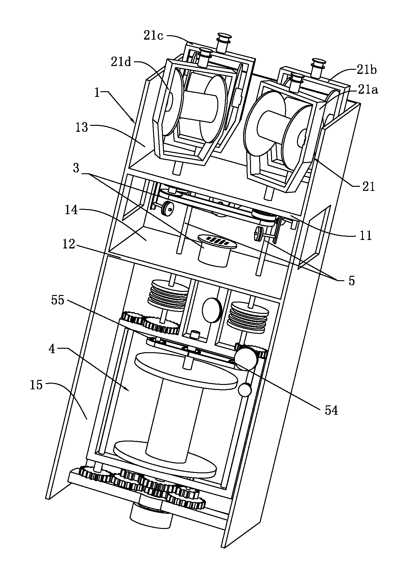
[0052] A kind of untwisting stranding machine described in this embodiment, such as Figure 1 to Figure 3 As shown, it includes a machine table 1, a wire feeding device 2, a stranding device 3, a wire winding device 4 and a transmission device 5. The machine table 1 is provided with a first working plate 11 and a second working plate 12, the first working plate 11 and the second working plate 12. The working plate 11 and the second working plate 12 divide the machine into three working chambers, namely the first working chamber 13, the second working chamber 14 and the third working chamber 15, the second working chamber The two sides of 14 are provided with through holes 141; the present invention divides the working chamber formed by the inner cavity of the machine table 1 into three, which is convenient to install each device inside, and has a simple structure and is not easy to cause confusion. The wire feeding device 2 includes at least one set of built-in wire feeding de...

Embodiment 2

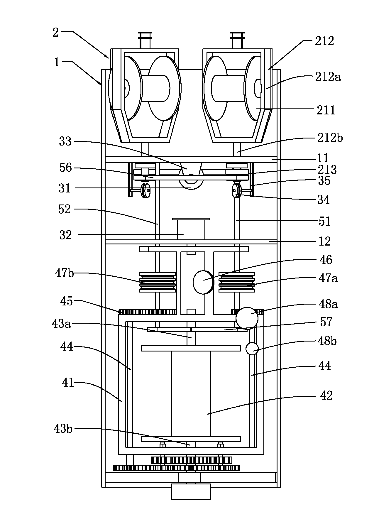
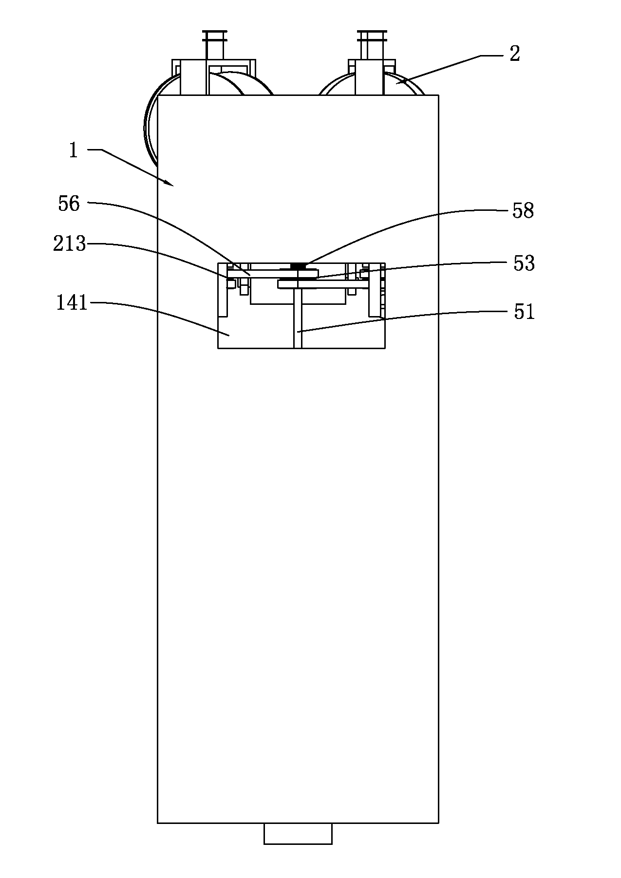
[0056] A kind of untwisting stranding machine described in this embodiment, such as Figure 1 to Figure 3 As shown, the difference between this embodiment and the first embodiment is that the wire feeding bracket 212 includes a bracket portion 212a and a hollow shaft 212b, the wire feeding wheel 211 is clamped on the bracket portion 212a, and the hollow shaft 212b passes through the frame portion 212a. Set on the lower end of the bracket portion 212a, the synchronizing gear I213 is sleeved on the hollow shaft 212b. The wire feeding support 212 in this embodiment is composed of a supporting part 212a and a hollow shaft 212b. The wire entering through the wire feeding wheel 211 can be transported downward along the hollow shaft 212b, and the wire feeding is stable and reliable.

[0057] Further, the stranding device 3 further includes a lead wheel 34 , and the lead wheel 34 is arranged below the hollow shaft 212 b through a fixing bracket 35 , and the fixing bracket 35 is fixedl...

Embodiment 3

[0060] A kind of untwisting stranding machine described in this embodiment, such as Figure 1 to Figure 3 As shown, the difference between this embodiment and the first embodiment is that the reeling device 4 further includes two interlocking rods 44, and the two interlocking rods 44 pass through the interlocking gear 45 and the synchronizing transmission rod 51 respectively. Connected to the support rod 52 respectively, the linkage gear 45 is arranged on the reel frame 41 . In this embodiment, when the synchronous transmission rod 51 rotates, the interlocking rod 44 can be driven to rotate at the same speed through the linkage gear 45, thereby driving the reel frame 41 to rotate at the same speed.

[0061] Further, the wire winding device 4 further includes a wire outlet wheel 46 , and the wire outlet wheel 46 is fixed to the wire winding frame 41 and located under the strand eye mold 32 . In this embodiment, after the wire rod is completely twisted in the stranding eye mold...


PUM


Abstract

The invention relates to the technical field of stranders, in particular to a back twist strander capable of eliminating torsion stress. The back twist strander comprises a stand, a feeding device, a stranding device, a transmission device and a coiling device, wherein the stand is provided with a first working plate and a second working plate which divide the stand into three working chambers. The back twist strander provided by the invention achieves the aim of eliminating torsion stress generated in the total stranding process of wires through controlling the rotating speed of a feeding end to be consistent with the rotating speed at a coiling end by using the same transmission device. The transmission device of the back twist strander transmits power through a synchronous transmissionrod as well as a synchronous gear and a synchronous belt which are in the same specification. The back twist strander is simple and compact in structure, capable of totally stranding a plurality of wires, varied in stranding way and high in stranding quality, and no jumping phenomenon is caused in the total stranding process of the wires.

Description

technical field [0001] The invention relates to the technical field of stranding machines, in particular to an untwisting stranding machine capable of eliminating torsional stress. Background technique [0002] Stranding machine is a widely used equipment in the wire and cable industry. twisted. In the process of stranding the above-mentioned wire, due to the asynchronous speed of the wire feeding device and the winding device, the wire is inevitably twisted during the stranding process, thereby generating a torsional stress, and the torsional stress will exist in the strand. It is wound on the outlet reel, which will seriously affect the quality of the stranded wire and the winding effect of the outlet reel. Especially when the wire outlet reel is full and the stranded wire outside the wire outlet reel needs to be cut to receive the material, the torsional stress in the wire strand will cause the wire at the end of the stranded wire to produce reverse torsional separation...

Claims


Application Information

Patent Timeline
Patent Type & Authority Applications(China)
IPC IPC(8): H01B13/02
Inventor 黄晖傅华良
Owner HUBEI YINGTONG ELECTRONICS
Why Eureka
Try Eureka