Back twist strander
A stranding machine and untwisting technology, applied in the field of stranding machines, can solve problems such as single stranding mode, low stranding quality, and easy jumping, and achieve high stranding quality, changeable stranding modes, and eliminate Effect of Torsional Stress
- Summary
- Abstract
- Description
- Claims
- Application Information
AI Technical Summary
Problems solved by technology
Method used
Image
Examples
Embodiment 1
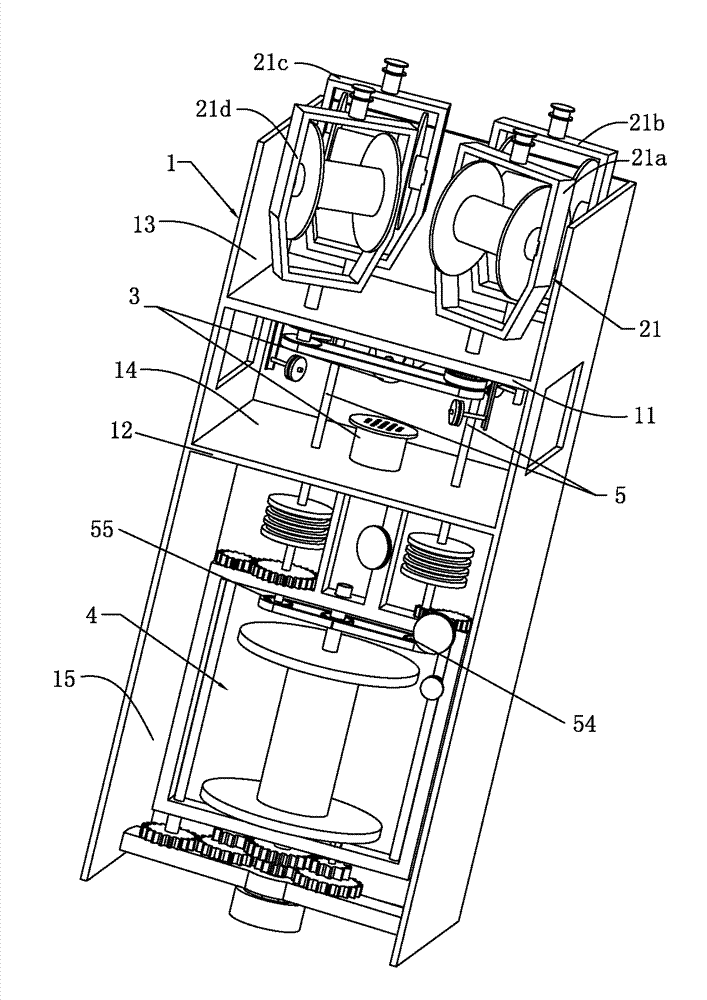
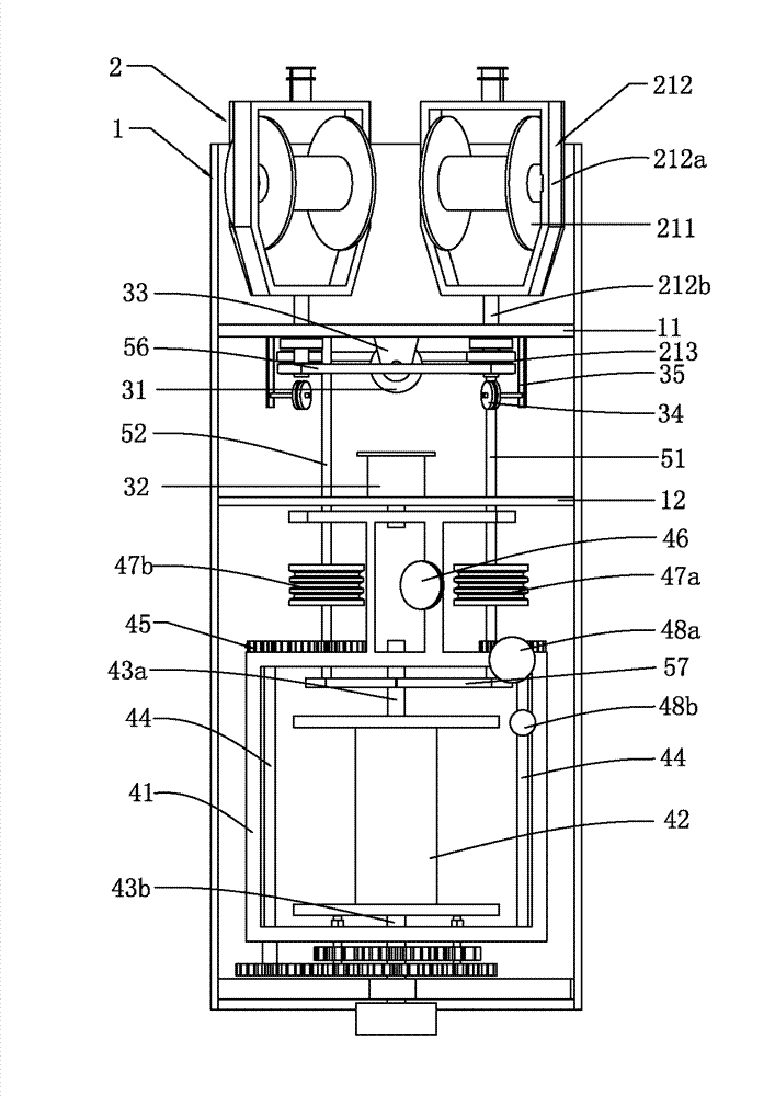
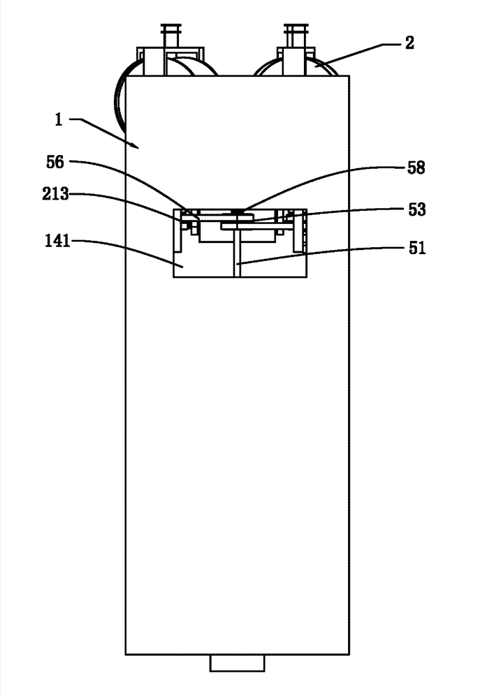
[0052] The untwisting and twisting machine described in this embodiment, such as Figure 1 to Figure 3 As shown, it includes an organic table 1, a wire feeding device 2, a wire twisting device 3, a wire winding device 4, and a transmission device 5. The machine table 1 is provided with a first working plate 11 and a second working plate 12, the first The working plate 11 and the second working plate 12 separate the machine into three working chambers, namely the first working chamber 13, the second working chamber 14 and the third working chamber 15, respectively. The second working chamber The two sides of 14 are provided with through holes 141; the present invention divides the working chamber formed by the inner cavity of the machine 1 into three, which is convenient for installing various devices inside, has a simple structure and is not easy to cause confusion. The wire feeding device 2 includes at least one set of built-in wire feeding devices 21, the built-in wire feedin...
Embodiment 2
[0056] The untwisting and twisting machine described in this embodiment, such as Figure 1 to Figure 3 As shown, the difference between this embodiment and the first embodiment is that the wire feeding bracket 212 includes a bracket portion 212a and a hollow shaft 212b, the wire feeding wheel 211 is clamped on the bracket portion 212a, and the hollow shaft 212b passes through Located at the lower end of the bracket portion 212a, the synchronous gear I213 is sleeved on the hollow shaft 212b. The wire feeding bracket 212 in this embodiment is composed of a bracket portion 212a and a hollow shaft 212b. The wire entering through the wire feeding wheel 211 can be conveyed downward along the hollow shaft 212b, and the wire feeding is stable and reliable.
[0057] Furthermore, the stranding device 3 further includes a lead wheel 34 which is arranged under the hollow shaft 212 b through a fixed bracket 35, and the fixed bracket 35 is fixedly installed on the machine table 1. By arrangin...
Embodiment 3
[0060] The untwisting and twisting machine described in this embodiment, such as Figure 1 to Figure 3 As shown, the difference between this embodiment and the first embodiment is that the winding device 4 further includes two linkage rods 44, and the two linkage rods 44 are respectively connected to a synchronous transmission rod 51 via a linkage gear 45. It is connected to the support rod 52 respectively, and the linkage gear 45 is arranged on the winding frame 41. In this embodiment, when the synchronous transmission rod 51 rotates, the linkage gear 45 can drive the linkage rod 44 to rotate at the same speed, thereby driving the winding frame 41 to rotate at the same speed.
[0061] Furthermore, the wire winding device 4 further includes a wire outlet wheel 46, which is fixed to the wire winding frame 41 and located below the stranding eye mold 32. In this embodiment, after the wire is stranded in the stranding die 32, the winding material can be conveyed along the wire exit ...
PUM
 Abstract
Description
Claims
Application Information
 - R&D
- Intellectual Property
- Life Sciences
- Materials
- Tech Scout
- Unparalleled Data Quality
- Higher Quality Content
- 60% Fewer Hallucinations
Browse by: Latest US Patents, China's latest patents, Technical Efficacy Thesaurus, Application Domain, Technology Topic, Popular Technical Reports.
© 2025 PatSnap. All rights reserved.Legal|Privacy policy|Modern Slavery Act Transparency Statement|Sitemap|About US| Contact US: help@patsnap.com


