
Method and device for sending measurement reference signal

A technology for measuring reference signals and control information, applied in the field of communications, can solve problems such as inability to judge when, asymmetric configuration of the transceiver antenna, and no solution proposed.

Inactive Publication Date: 2012-02-15
ZTE CORP
View PDF4 Cites 32 Cited by
  • Summary
  • Abstract
  • Description
  • Claims
  • Application Information

AI Technical Summary

Problems solved by technology

Part of the channel reciprocity problem refers to the asymmetric configuration of the UE's transceiver antennas. For example, the UE uses one transmit antenna for uplink and four receive antennas for downlink reception. When the base station needs to use channel reciprocity by measuring SRS For downlink transmission, since only one transmit antenna is used for uplink, the base station can only obtain part of the channel reciprocity, and can only use the downlink spatial multiplexing transmission with rank (Rank) as 1. At this time, the base station cannot judge what It is possible to transmit downlink with a rank of 2 or higher and what kind of precoding matrix to use
For this problem, no effective solution has been proposed

Method used


Image

  • Method and device for sending measurement reference signal
  • Method and device for sending measurement reference signal
  • Method and device for sending measurement reference signal

Examples


example 1

[0078] In this example, the user equipment selects an antenna or an antenna group to transmit the measurement reference signal according to an antenna mapping rule.

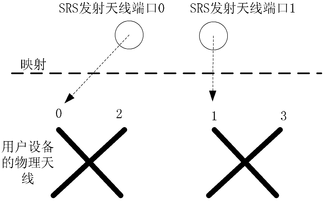
[0079] Such as figure 2 As shown, when the number of uplink SRS transmit antennas is 2 and the number of downlink receive antennas is 4, in order to solve some channel reciprocity problems, the SRS transmit antenna ports can be switched and mapped between physical transmit antennas in sequence at different SRS transmission times . For example, in the first transmission subframe of the SRS, the transmission port 0 of the SRS is mapped to the physical antenna 0, and the transmission port 1 of the SRS is mapped to the physical antenna 1; then in the second transmission subframe of the SRS, the transmission port 0 of the SRS Mapped to physical antenna 2, SRS transmit port 1 is mapped to physical antenna 3; in the third transmit subframe of SRS, SRS transmit port 0 is mapped to physical antenna 0, and SRS transmit p...

example 2

[0084] In this example, the user equipment selects an antenna or an antenna group to transmit the measurement reference signal according to an antenna selection rule.

[0085] The above antenna selection rules include:

[0086] The UE is at antenna index or group index a(n SRS ) on the antenna or group of antennas to transmit the nth SRS measurement reference signals, where each set of transmit antennas includes one or more transmit antennas, and the antenna index or antenna group index a(n SRS ) is determined as follows:

[0087] method one:

[0088] a(n SRS ) = n SRS mod2 or a(n SRS ) = n SRS mod4.

[0089] Method 2:

[0090] When SRS frequency hopping in the frequency domain is not enabled, a(n SRS ) = n SRS mod2 or a(n SRS ) = n SRS mod4;

[0091] When SRS frequency hopping in the frequency domain is enabled,

[0092]

[0093]

[0094] or

[0095] in is 1, N b′ The number of branches corresponding to layer b' when assigning the SRS bandwidth ...

example 3

[0098] In this example, the user equipment determines the antenna or antenna group to transmit the measurement reference signal according to the antenna selection mask in the downlink control information format.

[0099] The format of the downlink control information has a one-to-one correspondence with the antenna (port) of the user equipment or with the antenna (port) group, and the antenna (port) group includes one or more antennas (ports).

[0100] The downlink control information format is an information format that bears uplink scheduling information or bears downlink scheduling information, and the downlink control information formats include: format 4, format 2A, format 2B, and format 2C.

[0101] When the base station transmits multiple PDCCHs carrying antenna selection masks to the user equipment in a certain subframe, the base station may carry the same antenna selection mask on the multiple PDCCHs or the base station may carry the same antenna selection mask on one ...


PUM


Abstract

The invention discloses a method and a device for sending a measurement reference signal. The method comprises the following steps that: user equipment select an antenna or an antenna group to send the measurement reference signal, wherein the user equipment determine the antenna or the antenna group for sending the measurement reference signal according to an antenna mapping rule, or an antenna selection rule or an antenna selection mask in the format of downlink control information. With the technical scheme of the invention, the problem of reciprocity of some channels caused by the traditional standard methods is solved, so that a base station end can obtain integral downlink CSI (Channel State Information) based on the channel reciprocity, and the optimal pre-coding matrix can be used for each PRB (Physical Resource Block) during downlink transmission so as to obtain frequency selective pre-coding gain.

Description

technical field [0001] The present invention relates to the communication field, in particular, to a method and device for transmitting a measurement reference signal. Background technique [0002] In the 3rd Generation Partnership Project (The 3rd Generation Partnership Project, referred to as 3GPP) Long Term Evolution (LTE for short) system, the uplink signal includes a Physical Uplink Shared Channel (Physical Uplink Shared Channel, PUSCH for short) and Its demodulation reference signal (Demodulation Reference Signal for PUSCH), physical uplink control channel (Physical Uplink Control Channel, referred to as PUCCH) and its demodulation reference signal (Demodulation Reference Signal for PUCCH), measurement reference signal (Sounding Reference Signal, referred to as for SRS) and so on. [0003] A measurement reference signal (Sounding Reference Signal, SRS for short) is a signal used between a terminal device and a base station to measure wireless channel information (Chan...

Claims


Application Information

Patent Timeline
Patent Type & Authority Applications(China)
IPC IPC(8): H04B7/06H04L5/00
CPCH04B7/06H04B7/10H04L5/0023H04L5/0048H04L5/1469
Inventor 王瑜新陈艺戬郝鹏杨维维
Owner ZTE CORP
Learn More