Single-rod multi-head transecting spiral submersible pump

A technology of submersible oil pump and screw, which is applied in the field of single-rod multi-head cross-cut screw submersible pump, which can solve the problems of fast wear of the stator sleeve, many stages of impellers, and short service life, and achieve fewer structural moving parts, strong discharge pressure, and easy to use long life effect

Inactive Publication Date: 2013-09-18
石增辉
View PDF6 Cites 0 Cited by
  • Summary
  • Abstract
  • Description
  • Claims
  • Application Information

AI Technical Summary

Problems solved by technology

[0002] At present, there are general types of submersible pumps, such as multi-pole centrifugal submersible pumps, single-screw submersible pumps, etc. The efficiency of multi-pole centrifugal submersible pumps is low under high-pressure conditions, and there are many stages of impellers, requiring machining accuracy and assembly accuracy. High; single-screw submersible pump, the stator sleeve wears quickly, the failure rate is high, and the service life is short

Method used


Image

  • Single-rod multi-head transecting spiral submersible pump
  • Single-rod multi-head transecting spiral submersible pump
  • Single-rod multi-head transecting spiral submersible pump

Examples


Embodiment 1

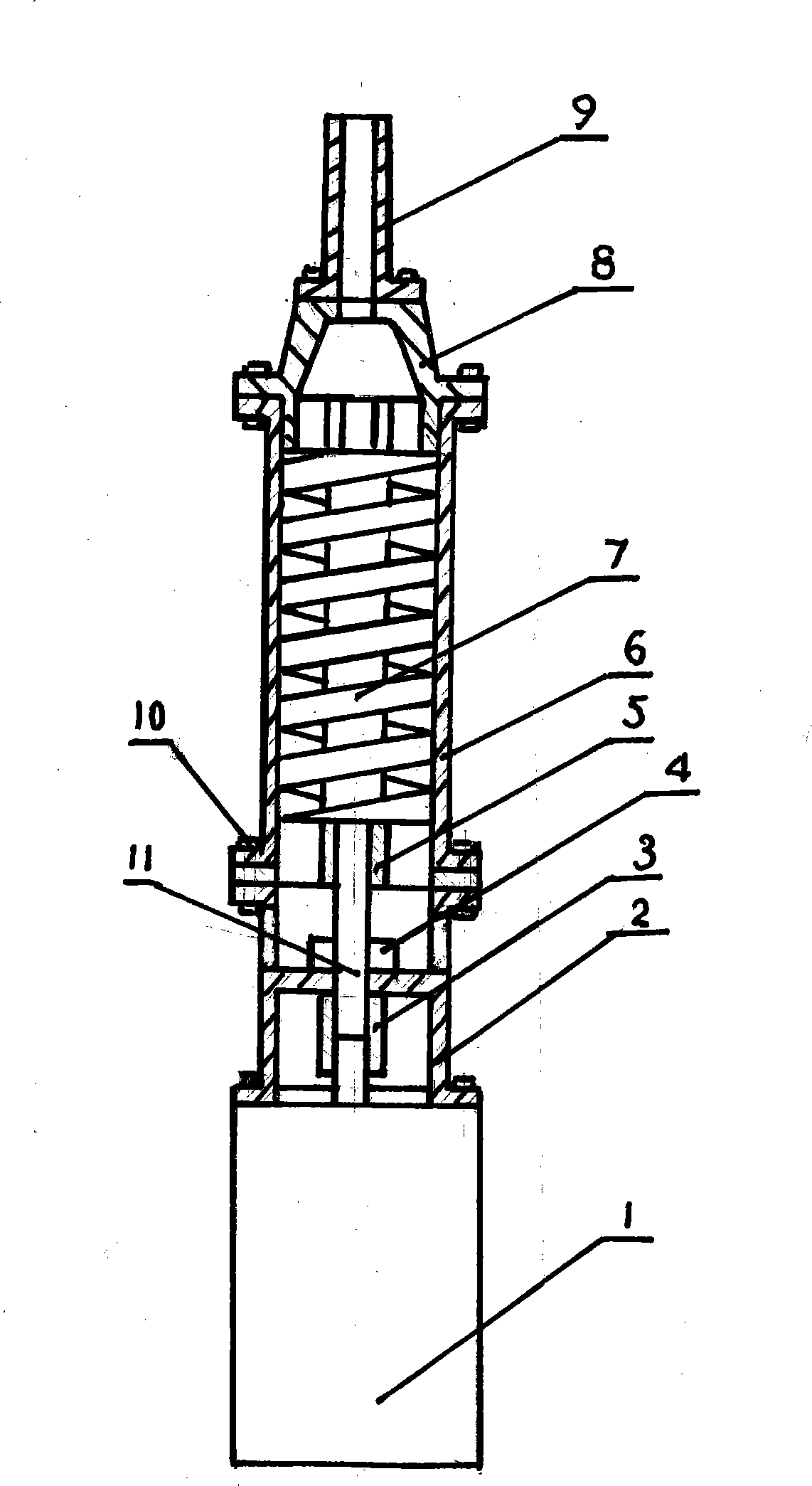
[0014] Embodiment 1, with reference to figure 1 , 2 , 4, a single-rod single-head cross-cut screw submersible pump, consisting of a submersible motor 1, a motor bracket 2, a coupling 3, a suction disc 5, a thrust bearing 4, a multi-head screw rotor 7, a housing 6, a collection and transportation Section 8, discharge pipe 9, and bolts 10, wherein the submersible motor 1 is connected to the suction disc 5 through the motor bracket 2, the coupling 3, the thrust bearing 4 is installed on the main shaft 11, and the multi-head helical rotor 7 is processed on the main shaft 11. The tooth end surface 13 of the multi-head helical rotor 7 cooperates with the rotating sliding surface of the suction disc 5 , the housing 6 is connected with the suction disc 5 through bolts 10 , and the upper end of the housing 6 is connected with the collecting joint 8 and the discharge pipe 9 .

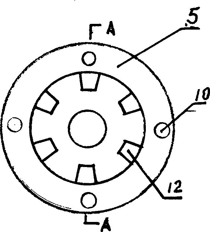
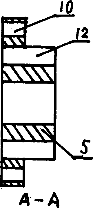
[0015] Said silk sucking and sparse dish 5 has six suction and sparse holes 12 equally divided on the suction...

Embodiment 2

[0017] Embodiment 2, with reference to figure 1 , 2 , 3, a single-rod three-head cross-cut screw submersible pump, consisting of a submersible motor 1, a motor bracket 2, a coupling 3, a suction disc 5, a thrust bearing 4, a multi-head screw rotor 7, a housing 6, a collection and transportation Section 8, discharge pipe 9, and bolts 10, wherein the submersible motor 1 is connected to the suction disc 5 through the motor bracket 2, the coupling 3, the thrust bearing 4 is installed on the main shaft 11, and the multi-head helical rotor 7 is processed on the main shaft 11. The tooth end surface 13 of the multi-head helical rotor 7 cooperates with the rotating sliding surface of the suction disc 5 , the housing 6 is connected with the suction disc 5 through bolts 10 , and the upper end of the housing 6 is connected with the collecting joint 8 and the discharge pipe 9 .

[0018] Said silk sucking and sparse dish 5 has six suction and sparse holes 12 equally divided on the suction ...


PUM


Abstract

The invention belongs to a pump, and in particular relates to a single-rod multi-head transecting spiral submersible pump. The single-rod multi-head transecting spiral submersible pump consists of a submersible motor, a motor bracket, a coupling, a suction and drainage disk, a thrust bearing, a multi-head spiral rotor, a shell, a gathering and delivering section, a discharge pipe and bolts, wherein the submersible motor is connected with the suction and drainage disk through the motor bracket and the coupling; the thrust bearing is arranged on a main shaft; the multi-head spiral rotor is machined on the main shaft; the tooth end face of the multi-head spiral rotor is matched with the rotary sliding surface of the suction and drainage disk; the shell is connected with the suction and drainage disk through the bolts; and the upper end of the shell is connected with the gathering and delivering section and the discharge pipe. The single-rod multi-head transecting spiral submersible pump has the advantages of strong discharge pressure, a few structural moving components, long service life and low cost, is particularly suitable for thick fluid media and long-distance transmission, and has the characteristics of energy conservation and high efficiency.

Description

technical field [0001] The invention belongs to pumps, more precisely, it is a single-rod multi-head cross-cut screw submersible pump. Background technique [0002] At present, there are general types of submersible pumps, such as multi-pole centrifugal submersible pumps, single-screw submersible pumps, etc. The efficiency of multi-pole centrifugal submersible pumps is low under high-pressure conditions, and there are many stages of impellers, requiring machining accuracy and assembly accuracy. High; single-screw submersible pump, the stator sleeve wears quickly, the failure rate is high, and the service life is short. Contents of the invention [0003] In view of this, the object of the present invention is to provide a single-rod multi-head transverse-cut screw submersible pump with high efficiency, energy saving and long service life. [0004] The purpose of the present invention is achieved through the following technical measures: a single-rod multi-head cross-cut sc...

Claims


Application Information

Patent Timeline
Patent Type & Authority Patents(China)
IPC IPC(8): F04D13/10F04D3/02
Inventor 石增辉
Owner 石增辉
Why Eureka
Try Eureka