

Screw piston pump
A piston pump and lead screw technology, applied in the direction of pumps, pump components, variable displacement pump components, etc., can solve the problems of large capacity, long distance, poor transmission capacity of high-viscosity medium, low power source capacity, etc., and achieve structural movement. Fewer components, powerful power, and low cost
Inactive Publication Date: 2008-04-30
王桐梅
View PDF0 Cites 14 Cited by
- Summary
- Abstract
- Description
- Claims
- Application Information
AI Technical Summary
Problems solved by technology
The transmission capacity of the pump depends on the power of the pump. The capacity of the power source of the traditional structure pump is relatively low, and the transmission capacity of large-capacity, long-distance, and high-viscosity media is poor.
Method used
View moreImage
Smart ImageViewing Examples

Examples
Embodiment 2
[0012] Embodiment 2. A lead screw piston pump is composed of two single-cylinder lead screw piston pumps as described in embodiment 1 and combined to form a double-cylinder lead screw piston pump.
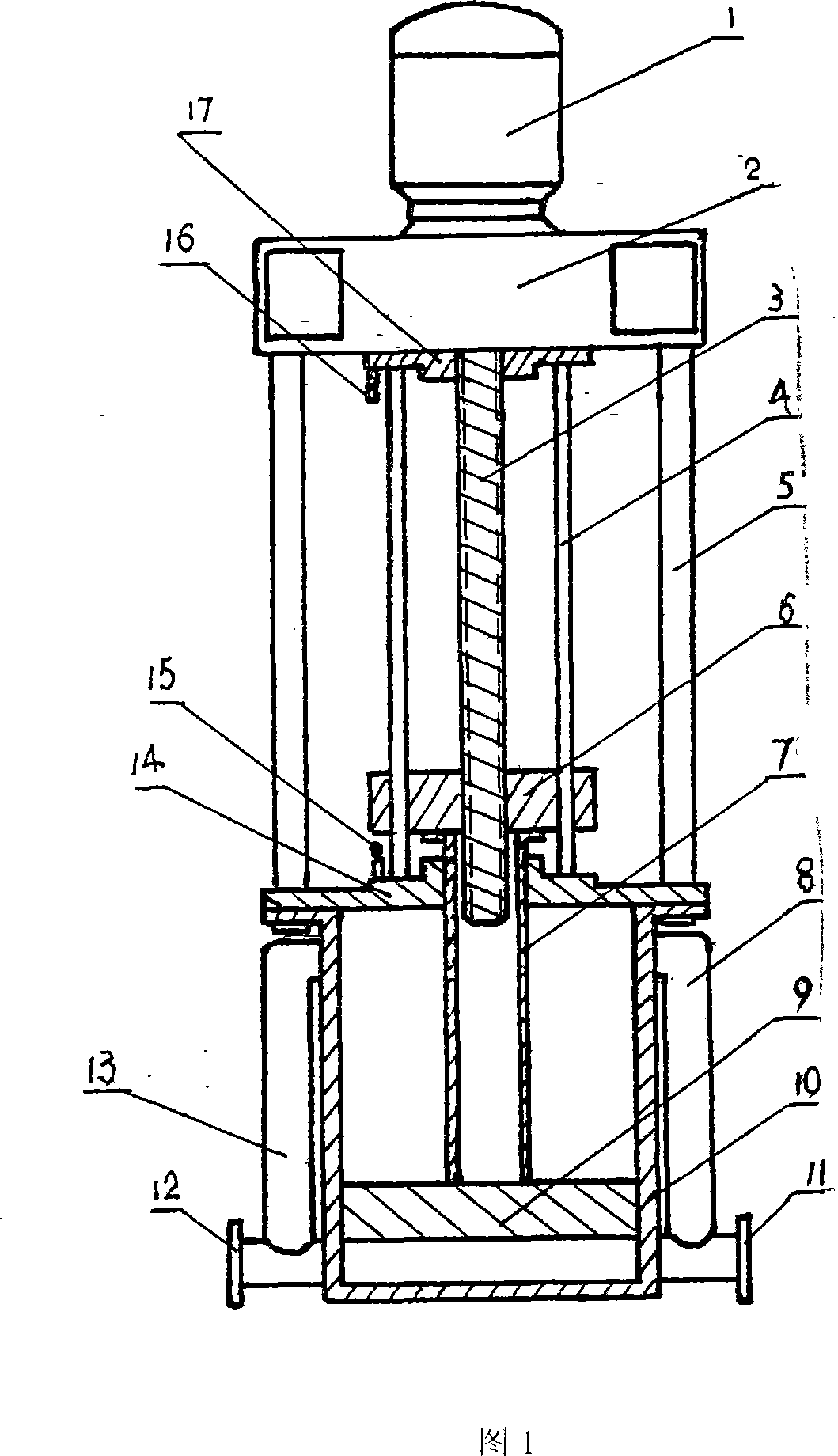
[0013] In the working state, when the piston is at the bottom of the cylinder, the lead screw pulls the piston upwards through the screw nut, and when it touches the upper limit switch, the screw nut moves down through the main shaft commutator and reciprocates.
Login to View More PUM
 Abstract
The invention belongs to a pump, in particular to a guide screw piston pump. The guide screw piston pump consists of an electromotor, a main shaft commutator, a guide screw, a nut leader, a connecting supported lever, a nut, a piston rod, a discharging valve, a piston, a cylinder, an outlet flange, an inlet flange, a sucking valve, an upper support seat, a lower support seat, a lower limit switch, and an upper limit switch. The piston, the piston rod, and the nut are connected together, and the nut and the guide screw are meshed. The invention adopts the structure that the piston, the piston rod and the nut are connected into a whole, the meshed motion of the nut and the guide screw is used as the power of the pump body, the discharging pressure is strong, the structural action parts are less, the cost is low, and the power is high. The invention is in particular applicable for the viscous medium and long-distance transmission, and is energy-saving and efficient.
Description
technical field [0001] The invention belongs to pumps, more precisely, it is a lead screw piston pump. Background technique [0002] At present, the general types of pumps include centrifugal type, diaphragm type, crankshaft piston type, etc. Pumps with various structures are suitable for the transmission of liquid and gaseous media. The transmission capacity of the pump depends on the power of the pump. The capacity of the power source of the traditional structure pump is relatively low, and the transmission capacity of large-capacity, long-distance, and high-viscosity media is poor. Contents of the invention [0003] In view of this, the object of the present invention is to provide a lead screw piston pump with higher power. [0004] The purpose of the present invention is achieved through the following technical measures: a lead screw piston pump, consisting of a motor, a main shaft commutator, a lead screw, a screw nut guide rod, a connecting support rod, a screw nut...
Claims
Login to View More Application Information
Patent Timeline
 Patent Type & AuthorityApplications(China)
IPC IPC(8): F04B17/03F04B53/14F04B53/10
Inventor石增辉
Owner王桐梅