
Luminaire

A technology of LED lamps and lamp sockets, which is applied in the directions of lampshades, instruments, lighting and heating equipment, etc., can solve the problems of poor light output angle, limited illumination range of LED lamps, and inconvenience.

Inactive Publication Date: 2012-03-14
LITE ON TECH CORP +1
View PDF11 Cites 11 Cited by
  • Summary
  • Abstract
  • Description
  • Claims
  • Application Information

AI Technical Summary

Problems solved by technology

[0003] However, compared with the comprehensive light output of ordinary incandescent bulbs, the general LED grain has a poorer light output angle (about 120 degrees) due to its own limitations, so that the application of LED lamps is limited by its light output angle. Compared with incandescent bulbs, the problem is that LED lamps can irradiate a limited range, and it is still unable to completely replace incandescent bulbs
For example, when an up-illuminated luminaire hung on the ceiling uses an incandescent bulb holder as the light source, the luminaire can simultaneously produce lighting functions on the ceiling and the space below the luminaire; but when the light source is replaced with an LED bulb, it can only be produced on the ceiling. lighting effect
[0004] It can be seen that the above-mentioned existing LED lamps obviously still have inconvenience and defects in structure and use, and need to be further improved urgently.
In order to solve the above-mentioned problems, the relevant manufacturers have tried their best to find a solution, but for a long time no suitable design has been developed, and the general product has no suitable structure to solve the above-mentioned problems. This is obviously the relevant industry. Urgent problem

Method used

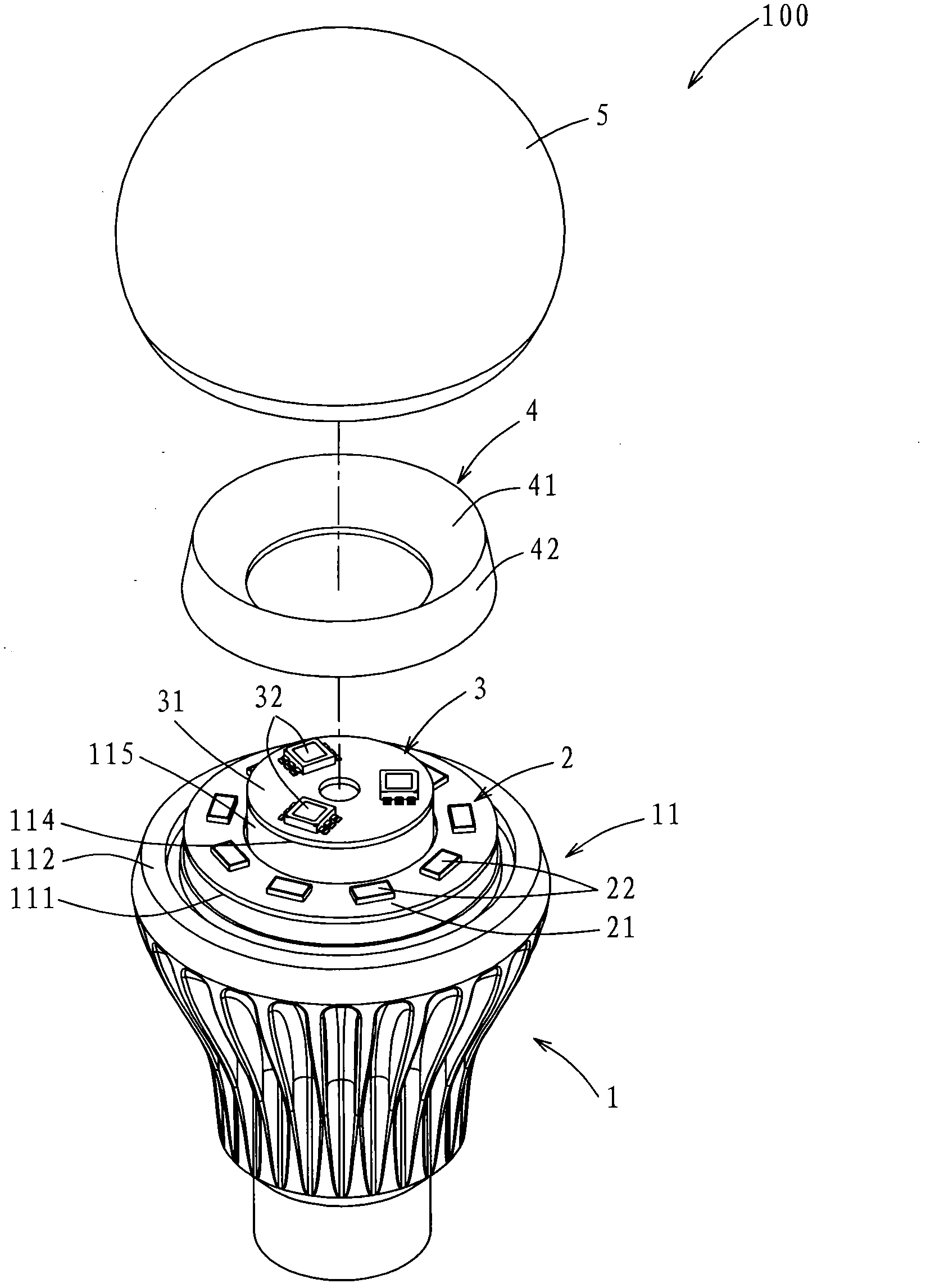
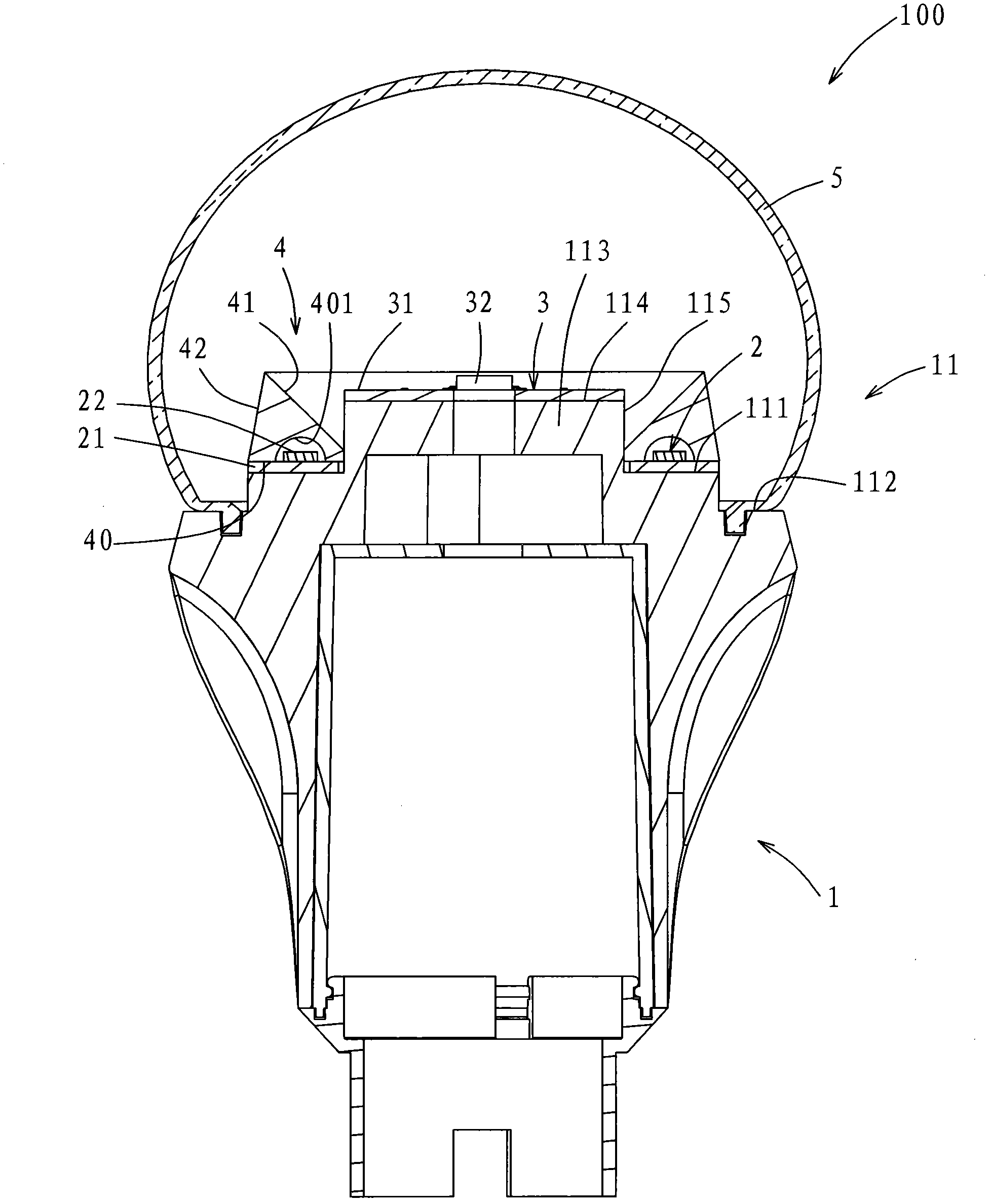
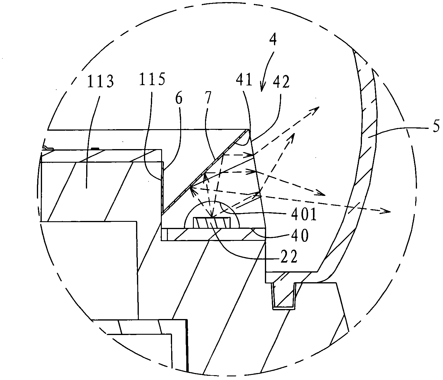

Image

  • Luminaire
  • Luminaire
  • Luminaire

Examples


Embodiment Construction

[0026] In order to further explain the technical means and effects of the present invention to achieve the intended purpose of the invention, the specific implementation, structure, features and effects of the LED lamp proposed according to the present invention will be described in detail below in conjunction with the accompanying drawings and preferred embodiments. The description is as follows.

[0027] refer to figure 1 , figure 2 and image 3 , The first preferred embodiment of the LED lamp of the present invention includes a lamp holder 1 , a first light-emitting module 2 , a second light-emitting module 3 , a light guide 4 , and a light-transmitting lampshade 5 .

[0028] The lamp holder 1 has a top 11, the top 11 includes a first top surface 111, a third top surface 112 which is lower in height than the first top surface 111 and surrounds the first top surface 111, and a 111 protruding boss 113 upwards. The first top surface 111 , the third top surface 112 , and t...


PUM


Abstract

A luminaire comprises a lamp holder, a first light-emitting module, a second light-emitting module, a light guide, and a lamp cover. The lamp holder has a top portion. The top portion includes a first upper face and a platform projecting upwardly from the first upper face. The platform has a second upper face at a top end thereof. The first light-emitting module is disposed on the first upper face and around the platform. The second light-emitting module is disposed on the second upper face. The light guide is disposed around the platform and on the first light-emitting module. The lamp cover is disposed on the lamp holder for covering the first light-emitting module, the second light-emitting module, and the light guide.

Description

technical field [0001] The present invention relates to an LED (light emitting diode, light emitting diode) lamp, in particular to an LED lamp providing a larger light emitting angle. Background technique [0002] General LED lamps have the advantages of power saving, long service life, small size, fast response, etc., and have been widely used in various electrical equipment and advertising billboards. [0003] However, compared with the comprehensive light output of ordinary incandescent bulbs, the general LED grain has a poorer light output angle (about 120 degrees) due to its own limitations, so that the application of LED lamps is limited by its light output angle. Compared with incandescent bulbs, the problem is that LED lamps can irradiate a limited range, and it is still unable to completely replace incandescent bulbs. For example, when an up-illuminated luminaire hung on the ceiling uses an incandescent bulb holder as the light source, the luminaire can simultaneou...

Claims


Application Information

Patent Timeline
IPC IPC(8): F21S2/00F21V8/00F21V17/00F21V19/00F21V13/00F21Y101/02
CPCF21S8/04F21V3/00F21V13/04F21K9/232F21Y2115/10
Inventor 梁志隆杨淑桦
Owner LITE ON TECH CORP
Learn More