Battery box fixing device

A technology of fixing device and battery box, applied in electric power device, power device, battery pack parts and other directions, can solve the problems of low versatility, inconvenient replacement and use of battery box, etc., and achieves strong versatility, convenient use and expanded availability. effect of space

Inactive Publication Date: 2012-03-21
ZHENGZHOU YUTONG BUS CO LTD
View PDF6 Cites 18 Cited by
  • Summary
  • Abstract
  • Description
  • Claims
  • Application Information

AI Technical Summary

Problems solved by technology

[0005] The purpose of the present invention is to provide a battery box fixing device with strong versatility and a certain quick replacement function to solve the problems of inconvenient battery box replacement and low versatility in the prior art

Method used


Image

  • Battery box fixing device
  • Battery box fixing device
  • Battery box fixing device

Examples


Embodiment 1

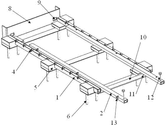
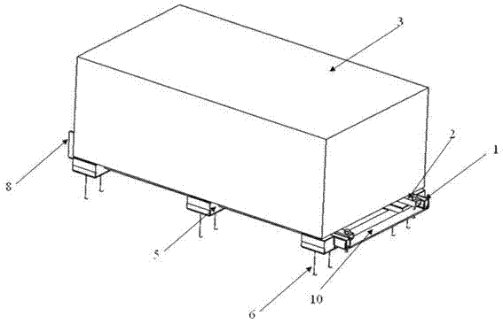
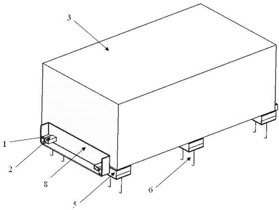
[0020] like Figure 1-4 The shown battery box fixing device includes a pair of linear rails 1 arranged in parallel, a chassis, and a guide rail 2 that is fixed to the battery box 3 and is parallel to the linear rail 1; the guide rails 2 can be installed (or Welding) at the bottom of the battery box 3 of any manufacturer. The upper end surface of the linear track 1 is provided with track rollers 4 for slidingly matching with the battery box 3 and carrying the battery box 3 to move along the track direction. The opposite inner surfaces of the two linear rails 1 are limit surfaces, which are used to coordinate with the guide rail 2. The limit guide rail 2 limits the movement (lateral movement) of the battery box in the direction perpendicular to the track (in the track surface). One end of the linear track 1 is the entry end for loading into the battery box, and the other end is a fixed end; the fixed end is fixed with a limit plate 8 for limiting the position of the battery box...

Embodiment 2

[0026] like Image 6 As shown, the difference between this embodiment and Embodiment 1 is that, unlike the shock absorbing pad 5 which is arranged between the underframe and the linear track 1, this embodiment adopts the shock absorbing cushion 14 arranged at the bottom of the underframe, and its The bottom is fixed with the car body by insulating plate 15.


PUM


Abstract

The invention relates to a battery box fixing device comprising a bottom frame, wherein a pair of parallel straight-line tracks is fixed on the bottom frame; the upper end surface of each straight-line track is provided with track rollers used for being contacted with the battery box; and one end of the pair of the straight-line tracks is provided with a limiting plate used for limiting the battery box. The straight-line tracks with rollers are utilized for carrying the battery box and guide rails fixed at the bottom of the battery box are utilized for limitation long the direction which the tracks face rightly. The fixed end of the battery box fixing device is provided with the limiting plate for retaining the battery box; and the limiting plate is provided with limiting holes for inserting the guide rails, therefore, the battery box fixing device can not only allow different models of battery boxes to be fixed on the guide rails, but also play a role of stabilizing the guide rail and the battery box.

Description

technical field [0001] The invention relates to the field of electric vehicles, in particular to a battery pack fixing device for an electric vehicle, that is, a battery box fixing device with versatility, shock absorption function and certain quick replacement function. Background technique [0002] With the continuous reduction of fossil energy on the earth, the continuous increase of greenhouse gases, and the continuous deterioration of the human living environment, governments of various countries have introduced stimulus policies to encourage the development of energy-saving and emission-reducing products. Although traditional fuel vehicles have brought many conveniences to people's lives, as a major polluter, they have attracted great attention from various countries. Special research plans have been introduced one after another to vigorously support and promote the development of the new energy vehicle industry. In particular, pure electric vehicles have been vigorous...

Claims


Application Information

Patent Timeline
Patent Type & Authority Applications(China)
IPC IPC(8): B60K1/04H01M2/10
CPCY02E60/10
Inventor 杜颖颖周时国董伟超邱鹏李龙
Owner ZHENGZHOU YUTONG BUS CO LTD
Why Eureka
Try Eureka