Clip detecting system and detecting method

A detection system and detection method technology, applied in the direction of measuring electricity, measuring devices, measuring electrical variables, etc., can solve problems such as time-consuming, laborious installation, wrong installation direction, and occupation of the total installation process, and achieve the effect of improving operational efficiency

Inactive Publication Date: 2012-03-21
上海李尔汽车部件有限公司
View PDF3 Cites 4 Cited by
  • Summary
  • Abstract
  • Description
  • Claims
  • Application Information

AI Technical Summary

Problems solved by technology

The traditional method is to use a marking rod to indicate the installation of the staples, but this method is easy to make the installation position of the staples inaccurate, the installation direction is wrong, or the wrong type

Method used


Image

  • Clip detecting system and detecting method
  • Clip detecting system and detecting method
  • Clip detecting system and detecting method

Examples


Embodiment 1

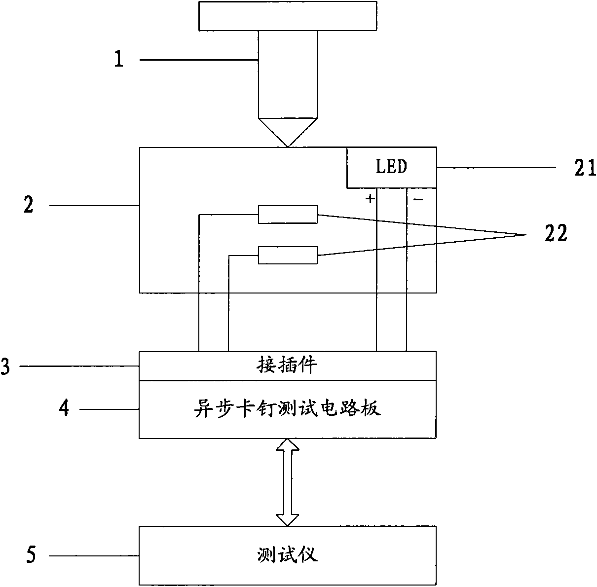
[0030] This embodiment provides a Clip detection system, such as figure 1 As shown, the detection system includes a staple 1 , an error-proof slot 2 , a connector 3 , an asynchronous staple test circuit board 4 , and a tester 5 . The staple 1 snaps into an anti-error slot 2 . The error prevention groove 2 is provided with LED 21 and switch pin 22, the LED pole leads out of the groove through a red wire, the LED negative pole leads out of the groove through a black wire, and the two ends of the switch needle 22 lead out of the groove through two non-red and black wires . The connector 3 is connected to the four lead wires of the error prevention slot 2 . The asynchronous staple test circuit board 4 is matched and plugged with the connector 3 to detect whether the staple 1 is correctly installed in the error prevention slot 2; the asynchronous staple test circuit board 4 is flattened by two 64-core The cable is connected with the tester 5 . The tester 5 is connected to the a...


PUM


Abstract

The invention discloses a Clip detecting system and a detecting method. The system comprises clips, a fail-safe groove, a connecting and inserting piece, an asynchronous clip testing circuit board and a tester. The clips are clamped in the fail-safe groove. A light-emitting diode (LED) and a switch needle are arranged in the fail-safe groove, an anode of the LED is guided out of the groove through a red guide line, a cathode of the LED is guided out of the groove through a black guide line, and two ends of the switch needle are guided out of the groove through two non-red and non-black guide lines. The connecting and inserting piece is connected with the four guide lines of the fail-safe groove. The asynchronous clamp testing circuit board is spliced with the connecting and inserting piece in matched mode and used for detecting whether the clips are arranged in the fail-safe groove correctly. The tester is connected with the asynchronous clamp testing circuit board and used for controlling test of all clips integrally. The Clip detecting system and the detecting method utilize the principle of comprehensive arrangement, effectively combine the two sections of the execution of test programs and practical operation of workers, simultaneously lead the indicating and guiding characteristics of the LED, bring the working efficiency of operators into full play, and improve operation efficiency exponentially.

Description

technical field [0001] The invention belongs to the technical field of electronic communication, relates to the test content of an automobile wire harness, and in particular relates to a Clip detection system and a detection method. Background technique [0002] Clip, also known as staple, is mainly installed on the wire harness to fix the wire harness on the vehicle body. The traditional method is to use a marking rod to indicate the installation of the staples, but this method is likely to cause inaccurate installation positions of the staples, wrong installation directions, or use of wrong types of staples. The staple test is an essential and basic test content for large automotive wiring harnesses, and it usually takes up most of the time in the total installation process, which is time-consuming and labor-intensive. Therefore, how to efficiently, time-saving, and simply complete the staple test becomes the key to solving this bottleneck. Contents of the invention ...

Claims


Application Information

Patent Timeline
IPC IPC(8): G01R31/00H02G3/00
Inventor 汪星
Owner 上海李尔汽车部件有限公司
Why Eureka
Try Eureka