Driving circuit, method and dimming controller for driving light source

A technology of dimming controller and driving circuit, applied in the field of driving circuit, can solve the problem that users cannot adjust the brightness, etc., and achieve the effect of saving cost

Active Publication Date: 2012-03-21
AOTU ELECTRONICS WUHAN
View PDF3 Cites 30 Cited by
  • Summary
  • Abstract
  • Description
  • Claims
  • Application Information

AI Technical Summary

Problems solved by technology

One of the disadvantages of this traditional solution is that the desired

Method used


Image

  • Driving circuit, method and dimming controller for driving light source
  • Driving circuit, method and dimming controller for driving light source
  • Driving circuit, method and dimming controller for driving light source

Examples


Embodiment Construction

[0031] Detailed reference will be given below to examples of the present invention. Although the present invention has been illustrated and illustrated by these embodiments, it should be noted that the present invention is not limited to these embodiments. On the contrary, the invention covers all alternatives, modifications and equivalents which are within the spirit and scope of the invention as defined by the appended claims.

[0032] In addition, in order to better illustrate the present invention, numerous specific details are given in the specific embodiments below. It will be understood by those skilled in the art that the present invention may be practiced without these specific details. In other instances, well-known methods, procedures, components and circuits have not been described in detail so as not to obscure the gist of the present invention.

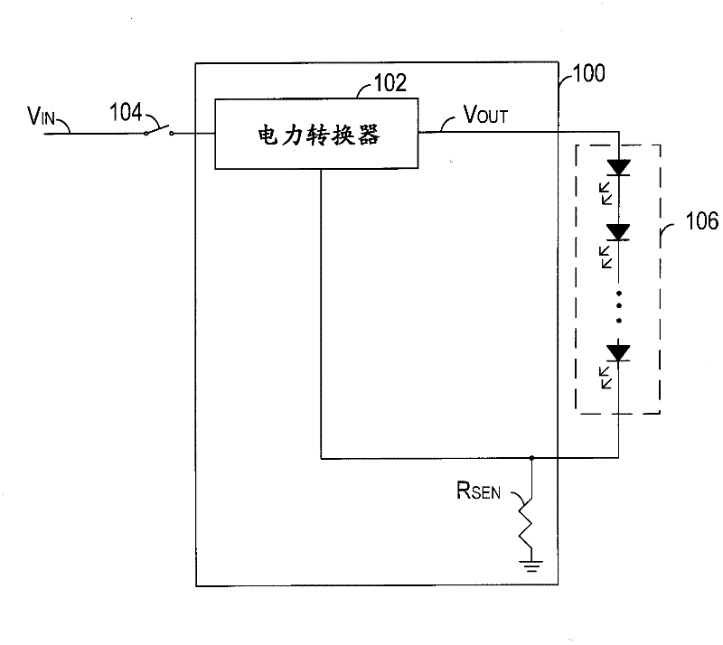
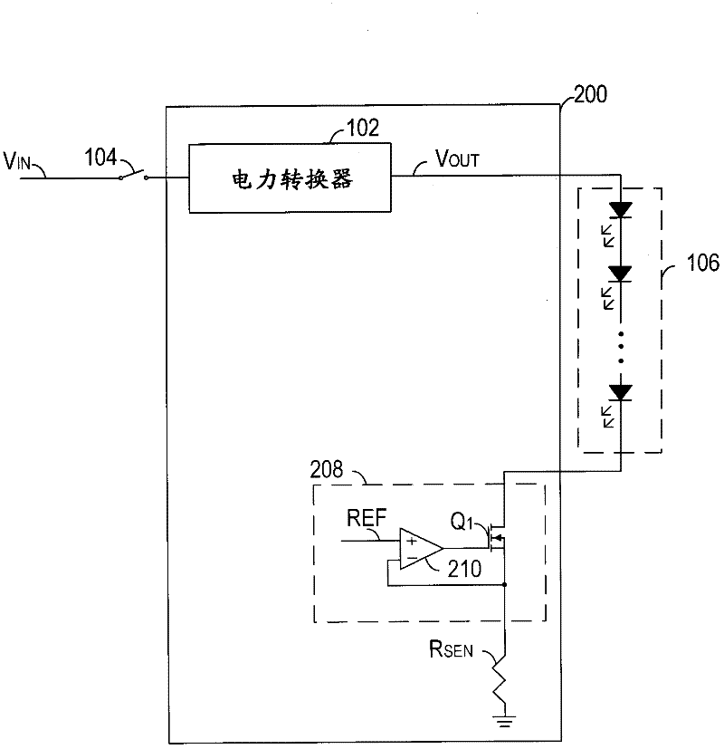
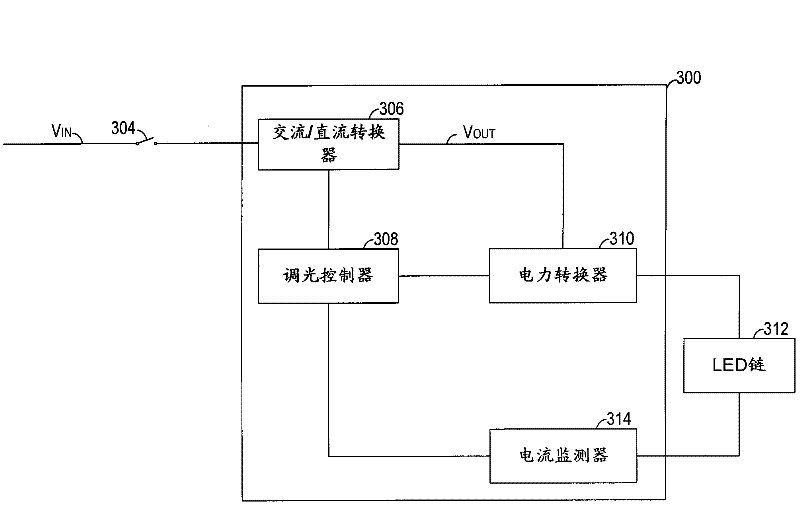
[0033] image 3 Shown is a block diagram of a light source driving circuit 300 according to one embodiment of the p...


PUM


Abstract

The invention discloses a driving circuit, a method and a dimming controller for driving a light source. The driving circuit includes a converter coupled to a power source and a dimming controller coupled to the converter. The converter is operable for receiving power from the power source and for providing regulated power to the light source according to control signals. The dimming controller is operable for monitoring a power switch coupled between the power source and the converter, for receiving a color change signal indicating a first set of operations of the power switch and a dimming request signal indicating a second set of operations of the power switch, for controlling the control signals to change the color of the light source in response to the color change signal, and for controlling the control signals to adjust the brightness of the light source in response to the dimming request signal. By using the driving circuit, the dimming controller and the method of the invention, a user can select the color of the light source by switching the ON/OFF status of the power switch and also can adjust the brightness of the light source by switching the ON/OFF status of the power switch. Extra dimming apparatuses are avoided and thus the cost is reduced.

Description

technical field [0001] The invention relates to a driving circuit, in particular to a circuit and a method for driving a light source. Background technique [0002] In recent years, new light sources such as light-emitting diodes (LEDs) have advanced both in materials and manufacturing. LED has the characteristics of high efficiency, long life, bright colors, etc., and can be used in the fields of automobiles, computers, communications, military and daily necessities. For example, LED lamps can replace traditional incandescent lamps as lighting sources. [0003] figure 1 Shown is a schematic diagram of a conventional LED driving circuit 100 . LED driver circuit 100 utilizes LED chain 106 as a light source. LED chain 106 includes a plurality of LEDs connected in series. The power converter 102 is used to convert the DC input voltage Vin into a desired DC output voltage Vout for powering the LED chain 106 . The switch 104 connected to the LED driving circuit 100 can conn...

Claims


Application Information

Patent Timeline
IPC IPC(8): H05B37/02H05B44/00
CPCH05B33/0866H05B33/0857H05B45/24H05B45/20H05B45/10
Inventor 郭清泉林永霖
Owner AOTU ELECTRONICS WUHAN
Why Eureka
Try Eureka