Permanent magnet controlled metal button switch

A metal and button technology, which is applied in the field of permanent magnet control metal button switches, can solve the problems of unreasonable magnetic field circuit design, small operating force, poor magnetic shielding, etc., and achieve reasonable magnetic field circuit design, large operating force, and no magnetic leakage Effect

Inactive Publication Date: 2012-03-28
江苏双科电气有限公司
View PDF0 Cites 0 Cited by
  • Summary
  • Abstract
  • Description
  • Claims
  • Application Information

AI Technical Summary

Problems solved by technology

In order to make the button switch waterproof and insulating, a sealing ring is provided between the head of the button switch and the switch part, but none of them are really completely waterproof and insulated.
Through the search, it is found that some patents of permanent magnet push button switches have been published in my country, but they generally have the following defects: unreasonable design of the magnetic field circuit and the use of large magnets, small actuation force, poor magnetic shielding, and serious magnetic flux leakage

Method used


Image

  • Permanent magnet controlled metal button switch
  • Permanent magnet controlled metal button switch
  • Permanent magnet controlled metal button switch

Examples


Embodiment Construction

[0011] The specific content of the present invention will be described in detail below in conjunction with the accompanying drawings and specific embodiments.

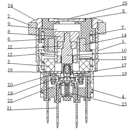
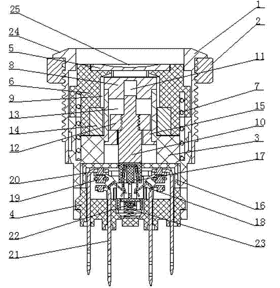
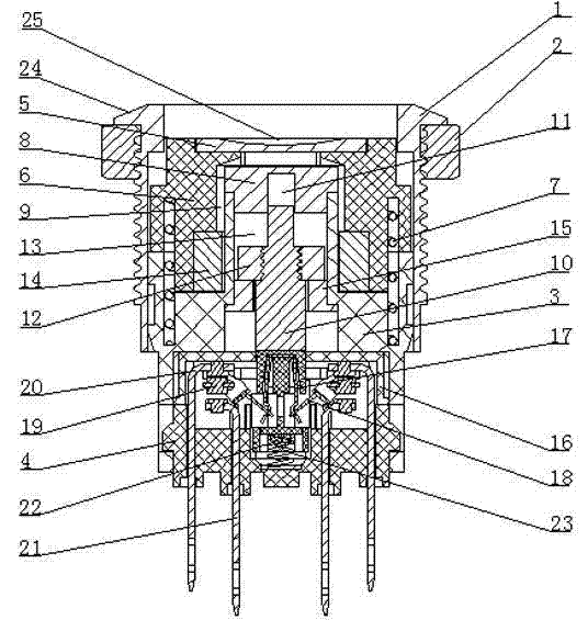
[0012] like figure 1 , figure 2 As shown, the permanent magnet control metal button switch includes: a metal shell 1, a fastening ring 2 arranged on the outside of the metal shell 1, and the lower end of the metal shell 1 passes through the connecting piece 3 and the contact base 4; The upper end of the metal shell 1 is provided with a cap 5 and a lens seat 6, a compression spring 7 is provided between the lens seat 6 and the connecting piece 3, and a first movable chamber that cooperates with the upper armature 8 is provided in the lens seat 6. 9. In the upper armature 8, there is a second movable chamber 11 that cooperates with the upper end of the piston rod 10. The piston rod 10 is provided with a piston 12, and the piston 12 and the piston rod 10 are movably arranged in the third movable chamber in the connectin...


PUM


Abstract

The invention discloses a permanent magnet controlled metal button switch which has a reasonable magnetic field loop design and a good water-proof insulation effect. The switch comprises a metal shell, a fastening ring, a connection piece, a contact base frame, a cap, a lens base, a pressing spring, an upper armature, a first moving cavity, a piston rod, a second moving cavity, a piston, a third moving cavity, a magnetic ring, a lower armature, a contact support, a spring sheet, a contact bridge, a moving contact, an upper static contact, a lower static contact, a top rod and a spring, wherein the fastening ring is arranged at the outer side of the metal shell; the lower end of the metal shell penetrates through the connection piece and the contact base frame; the cap and the lens base are arranged inside the upper end of the metal shell; the pressing spring is arranged between the lens seat and the connection piece; the first moving cavity which is mutually matched with the upper armature is arranged in the lens seat; the second moving cavity which is mutually matched with the upper end of the piston rod is arranged in the upper armature; the piston rod is provided with the piston; the piston and the piston rod are movably arranged in the third moving cavity in the connection piece; the magnetic ring which is mutually matched with the piston is arranged at the outer side of the connection piece; the lower armature is arranged on the lower end of the third moving cavity; the contact support, the spring sheet, the contact bridge, the moving contact, the upper static contact, the lower static contact, the top rod and the spring are arranged between the connection piece and the contact base frame; and the upper end of the spring sheet props against the lower end of the piston rod.

Description

technical field [0001] The invention relates to a push button switch, in particular to a permanent magnet control metal push button switch. Background technique [0002] At present, domestic and foreign pushbutton switches generally all make head movements to directly touch the switch part. In order to make the push button switch have a waterproof and insulating effect, a sealing ring is provided between the head of the push button switch and the switch part, but all do not really achieve complete waterproof insulation. Through search, it is found that some patents of permanent magnet push button switches have been published in my country, but they generally have the following defects: unreasonable design of the magnetic field circuit and the use of large magnets, small actuation force, poor magnetic shielding, and serious magnetic flux leakage. Contents of the invention [0003] The technical problem to be solved by the present invention is to provide a permanent magnet ...

Claims


Application Information

Patent Timeline
Patent Type & Authority Applications(China)
IPC IPC(8): H01H13/20H01H36/00
Inventor 王金辉张本兵
Owner 江苏双科电气有限公司
Why Eureka
Try Eureka