Method, device and system for simulating network element
A technology for simulating network elements and network management systems, applied in transmission systems, digital transmission systems, electrical components, etc., can solve problems that affect the normal operation of services
- Summary
- Abstract
- Description
- Claims
- Application Information
AI Technical Summary
Problems solved by technology
Method used
Image

Examples
Embodiment 1
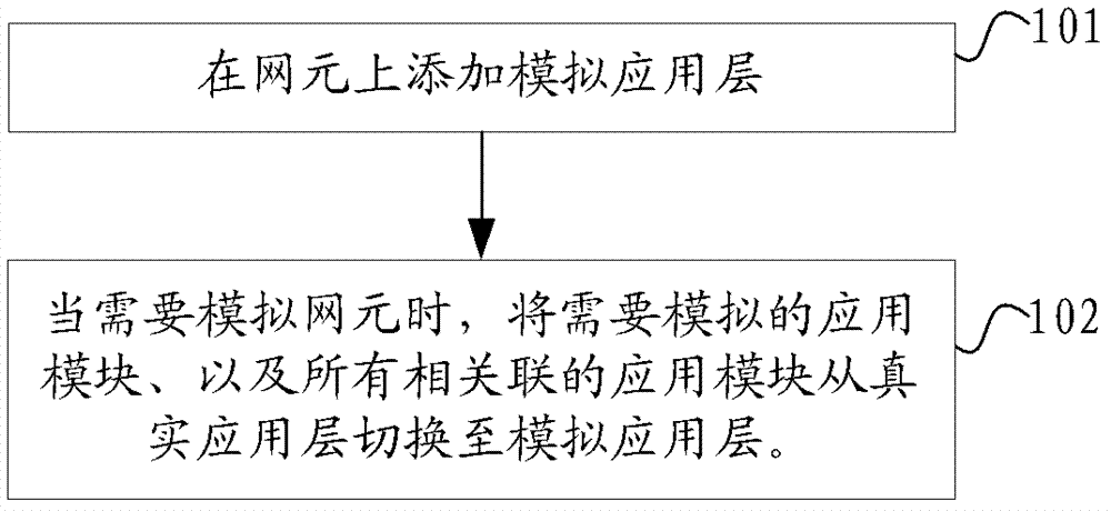
[0023] Such as figure 1 Shown is a flow chart of a method for simulating a network element provided in Embodiment 1, in the figure:
[0024] Step S101, adding a simulated application layer on a real network element;
[0025] Specifically, a simulated application layer is added to the real network element, and the application modules of the simulated application layer correspond to the application modules of the real layer, and the configuration thereof comes from the real application layer. The simulated application layer is disabled by default, and is completely isolated from the real application layer by default.
[0026] Step S102, when the network element needs to be simulated, switch the application module to be simulated and all associated application modules from the real application layer to the simulated application layer.
[0027] Preferably, in order to ensure that after the simulated application layer is enabled, the business of the real application layer runs no...
Embodiment 2
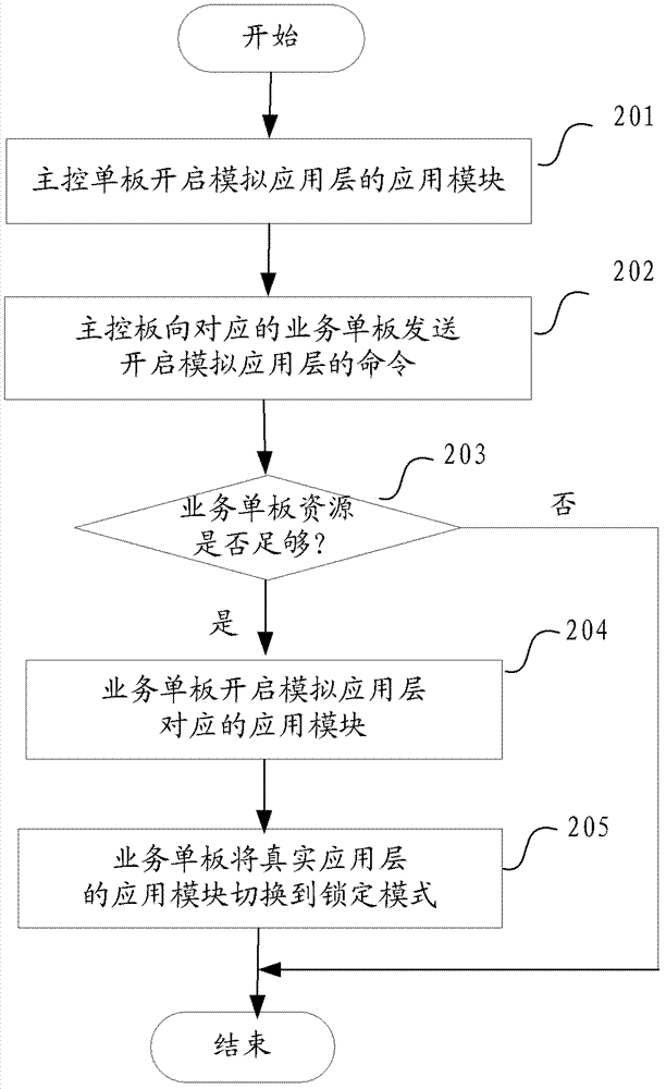
[0029] Such as figure 2 Shown is a flow chart of a method for enabling a simulated application layer on a main control board and a service board provided in Embodiment 2. In the picture:
[0030] In step S201, the main control board starts the application module corresponding to the simulated application layer after receiving the command to activate the simulated application layer from the network management system.
[0031] Specifically, after receiving the command to activate the simulated application layer issued by the network management system, the main control board first analyzes the parameters and content carried in the command to acquire the functions that need to activate the simulated application layer. Find the application modules to be simulated and all associated application modules according to the functions to be simulated, and the slot numbers of the service boards corresponding to these application modules; then start the corresponding application modules i...
Embodiment 3
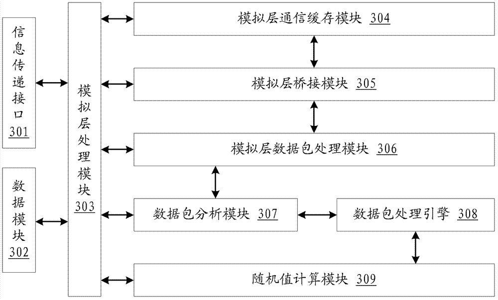
[0042] Such as image 3 Shown is a structural block diagram of a device for simulating a network element provided in Embodiment 3 of the present invention. In addition to the simulated application layer application module corresponding to the real layer application layer application module, the device also includes an information transfer interface 301 and a data module 302 And simulation layer processing module 303, wherein:
[0043] The information transfer interface 301 is used to transfer information with the application modules of the real layer, and to communicate with the network management system in real time;
[0044] Data module 302: storing data of the simulated application layer;
[0045] The simulation layer processing module 303 is responsible for the scheduling and processing of all simulation application layer application modules. The core of the simulation layer can be realized by a chip.
[0046] Preferably, in order to be able to compare the data synchroni...
PUM
 Abstract
Description
Claims
Application Information
 - R&D Engineer
- R&D Manager
- IP Professional
- Industry Leading Data Capabilities
- Powerful AI technology
- Patent DNA Extraction
Browse by: Latest US Patents, China's latest patents, Technical Efficacy Thesaurus, Application Domain, Technology Topic.
© 2024 PatSnap. All rights reserved.Legal|Privacy policy|Modern Slavery Act Transparency Statement|Sitemap