Check patentability & draft patents in minutes with Patsnap Eureka AI!

System for controlling electrical equipment units

A technology of electrical equipment and autonomous control, applied in the direction of control/regulation systems, electrical components, logic controllers for automation/industrial process control, etc., can solve expensive and complex problems, achieve easy maintenance, minimize interruption, The effect of reducing inventory costs

Inactive Publication Date: 2012-03-28
ORGA HLDG
View PDF4 Cites 0 Cited by
  • Summary
  • Abstract
  • Description
  • Claims
  • Application Information

AI Technical Summary

Problems solved by technology

[0003] A disadvantage of the systems described above is that they are relatively complex and expensive to manufacture, install, maintain and / or repair

Method used


Image

  • System for controlling electrical equipment units
  • System for controlling electrical equipment units
  • System for controlling electrical equipment units

Examples


Embodiment Construction

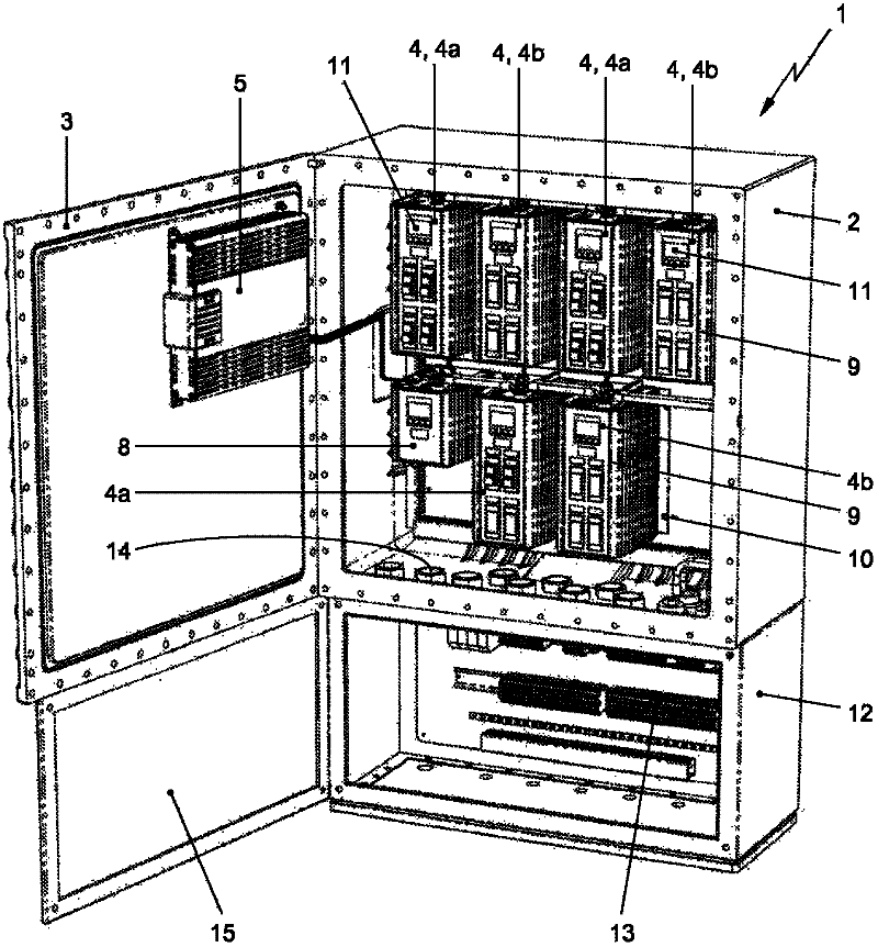
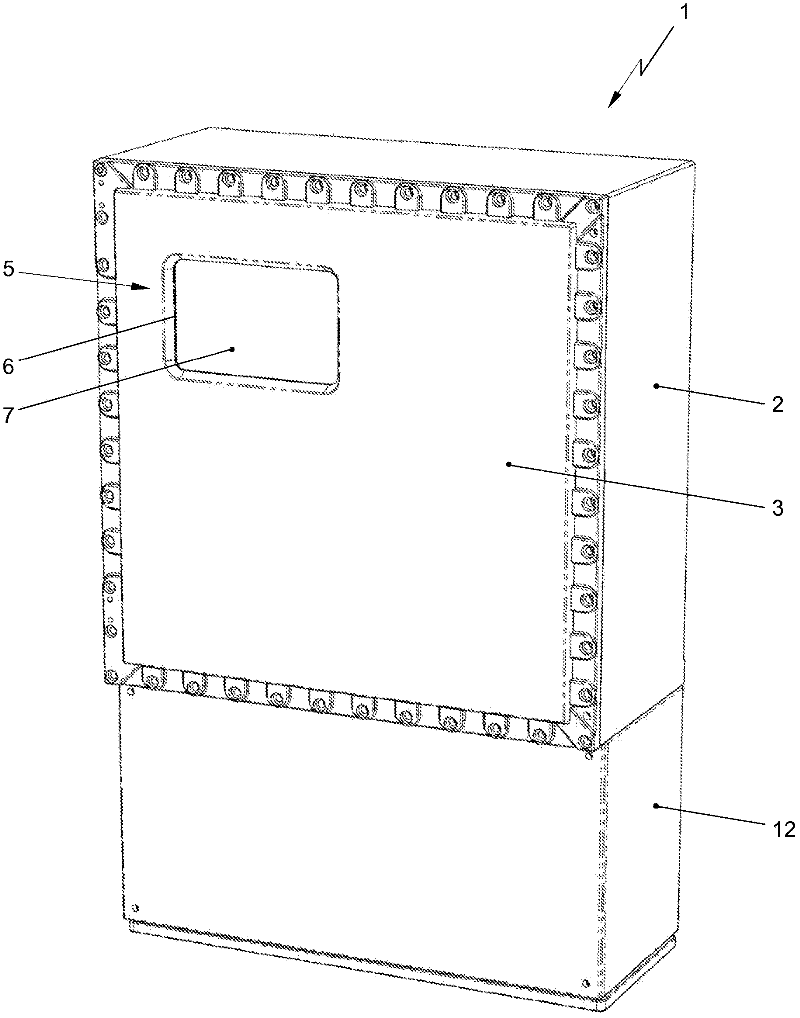
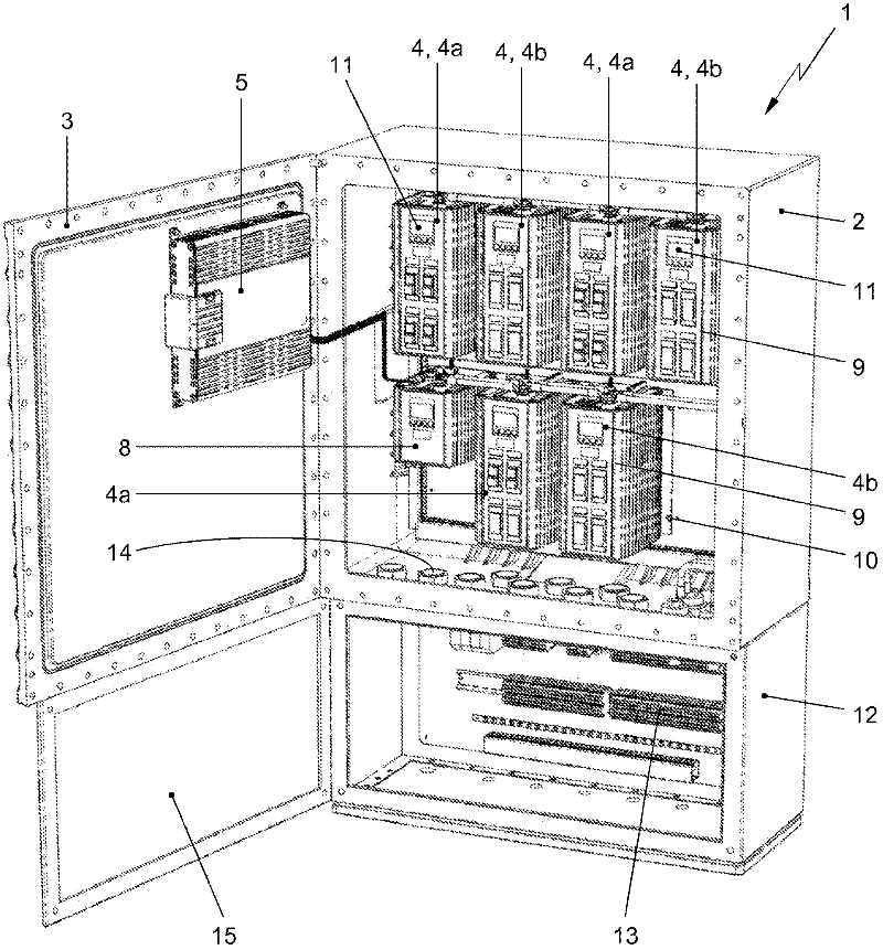
[0044] figure 1 A system 1 for controlling an electrical equipment unit is disclosed. The system 1 is here a control panel comprising a housing 2 which can be closed with a paneled door 3 . Such a system 1 may be placed on an offshore structure for controlling peripheral equipment such as navigation aid lighting units, obstruction lighting units, helideck lighting units, fog horn units, solar panel units or battery system units. The system 1 may be arranged as a navigation assistance central control panel (NCCP), adapted to operate navigation assistance peripherals. The system 1 may also be placed on a land structure, such as a tower building, for example to control obstruction lighting fixtures placed on the structure.

[0045] On offshore structures the system 1 is usually ensured to be explosion proof. Therefore, the enclosure 2 and the paneled door 3 must comply with the requirements for explosion-proof equipment. The outer shell 2 and the paneled door 3 may be reinfor...


PUM


Abstract

System for controlling electrical equipment units on an offshore structure comprising an explosion proof housing closable with a panel door, at least one controller module mountable in the housing, arranged for autonomously controlling an electrical equipment unit, wherein the panel door comprises an operating module arranged for operating the at least one controller module and for providing status indication of the at least one controller module.

Description

technical field [0001] The invention relates to a system for controlling electrical equipment units on an offshore structure. Background technique [0002] It is well known in the art to control electrical equipment units or peripherals, such as navigation aids, via a main switch box. Switchboxes typically include an enclosure that can be closed with a paneled door. Mounted in the housing are various electronic components such as switches, fuses, relays, printed circuit boards and transformers, which are electrically connected to each other via wires such that output signals for eg one or more lamps are generated. On the paneled door, one or more indicators (usually lights) are provided to indicate the status of the electronic components and / or light fixtures. For example, a green light indicates a working state, and a red light indicates a fault state. Likewise, operating buttons and / or switches (when used to operate the light fixture) are provided on the paneled door. ...

Claims


Application Information

Patent Timeline
Patent Type & Authority Applications(China)
IPC IPC(8): H05K7/14H02B1/28
CPCH02B1/28H05K7/1481H05K7/1467G01F23/284G05D7/00G05D11/00H05K5/00H05K5/06H05K7/14
Inventor 彼得·赫拉尔杜斯·戈德克内格特罗伯托斯·埃夫拉尔杜斯·安东尼厄斯·范德海登威廉默斯·雅各布斯·玛丽亚·斯米特约翰内斯·阿里·德布鲁杰恩
Owner ORGA HLDG
Features
  • R&D
  • Intellectual Property
  • Life Sciences
  • Materials
  • Tech Scout
  • Unparalleled Data Quality
  • Higher Quality Content
  • 60% Fewer Hallucinations
Learn More