
Active delay device in streaming media transmission system based on universal series bus

A streaming media transmission, serial bus technology, applied in transmission systems, electrical components, etc., can solve the problem that terminal equipment cannot be effectively synchronized, and achieve the effect of low cost and simple structure

Active Publication Date: 2015-05-20
BEIJING PHILISENSE TECH
View PDF2 Cites 0 Cited by
  • Summary
  • Abstract
  • Description
  • Claims
  • Application Information

AI Technical Summary

Problems solved by technology

However, in this new serial streaming media bus structure, there is a problem that different terminal devices cannot effectively synchronize when executing commands, that is, a certain action cannot be executed at the same time strictly according to the command of the central control device, or they cannot be executed separately. End devices are able to perform their actions at strict time intervals

Method used


Image

  • Active delay device in streaming media transmission system based on universal series bus
  • Active delay device in streaming media transmission system based on universal series bus
  • Active delay device in streaming media transmission system based on universal series bus

Examples


no. 1 approach

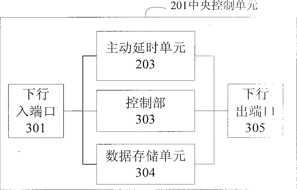
[0020] attached figure 2 The overall system structure of the serial bus-based streaming media transmission system according to an embodiment of the present invention is shown. Wherein the system includes a plurality of terminal devices 202-1, 202-2, ..., 202-n and a central control device 201, and the multiple terminal devices 202-1, 202-2, ..., 202-n are connected in series , and the central control device 201 is connected to a terminal device 202-1 at the front end of the serially connected terminal devices, wherein signals from each of the terminal devices are serially transmitted upstream to the central control device, And the signal from the central control device is serially transmitted downlink to the terminal device corresponding to the signal, the central control device is provided with an active delay unit 203 (the specific structure is described below) to connect, each terminal The devices 202-1, 202-2, ..., 202-n are respectively provided with timers 204-1, 202-4...

no. 2 approach

[0043] The second embodiment is basically the same as the first embodiment, the only difference being that the above-mentioned active delay units 203 are respectively arranged outside the central control device 201 and connected with the central control device.

[0044] Correspondingly, the time stamp data generated in each terminal device for calculating the transmission delay Tt between the central control device and each terminal device, and the time stamp data generated in each terminal device for calculating the execution delay are in After the uplink transmission to the central control device, it will be further provided to the active delay unit through the central control device. After the active delay unit calculates the active delay for each terminal device, it will be provided to the central control device for the central control device to follow The same method as above is issued to the corresponding terminal equipment.


PUM


Abstract

An active delay device in a streaming media transmission system based on a universal series bus is provided and comprises a transmission delay determining unit, an actuating delay determining unit, an intrinsic delay determining unit, an intrinsic delay, a comparator, an active delaying arrangement unit, an active delay value, wherein the intrinsic delay is used for calculating each terminal device according to the transmission delay and the actuating delay, and the active delay value is used for determining each terminal device according to a maximum intrinsic delay value and the intrinsic delay of each terminal device. The terminal devices which need to perform control commands in the same frequency can accurately be synchronized, or each terminal device can perform each action according to strict time intervals, particularly in a sound mixing system, the fact that each terminal device strictly performs displaying of sound mixing signals at the same time is effectively ensured, and echo is prevented from being generated.

Description

technical field [0001] The invention relates to a system for real-time data transmission using a serial bus. In particular, it involves precise synchronous control of data processing performed by all devices on the serial bus on the basis of comprehensive consideration of transmission delay for various occasions such as multimedia on-site conferences and industrial control. Background technique [0002] The applicant of this application proposed a Chinese invention patent application with an application date of 2009 / 04 / 24, an application number of 200910135666.7, and an invention title of "A Digital Voice Transmission System Based on a Local Area Network". The continuous and real-time LAN-based voice digital transmission system provides high-quality digital voice transmission. The system includes multiple terminal devices 202-1, 202-2, ..., 202-n and a central control device 201, characterized in that: the multiple terminal devices 202-1, 202-2, ..., 202- n are connected i...

Claims


Application Information

Patent Timeline
Patent Type & Authority Patents(China)
IPC IPC(8): H04L29/06
Inventor 杨振华曹忻军施亮
Owner BEIJING PHILISENSE TECH
Learn More