Gating fluorescence service life imaging device based on light delay
A fluorescence lifetime and imaging device technology, applied in fluorescence/phosphorescence, material excitation analysis, etc., can solve the problems of high delay accuracy hardware performance requirements, increase system complexity, unsolved transient fluorescence imaging problems, etc., and achieve high imaging Efficiency, the effect of simple installation
- Summary
- Abstract
- Description
- Claims
- Application Information
AI Technical Summary
Problems solved by technology
Method used
Image
Examples
Embodiment 1
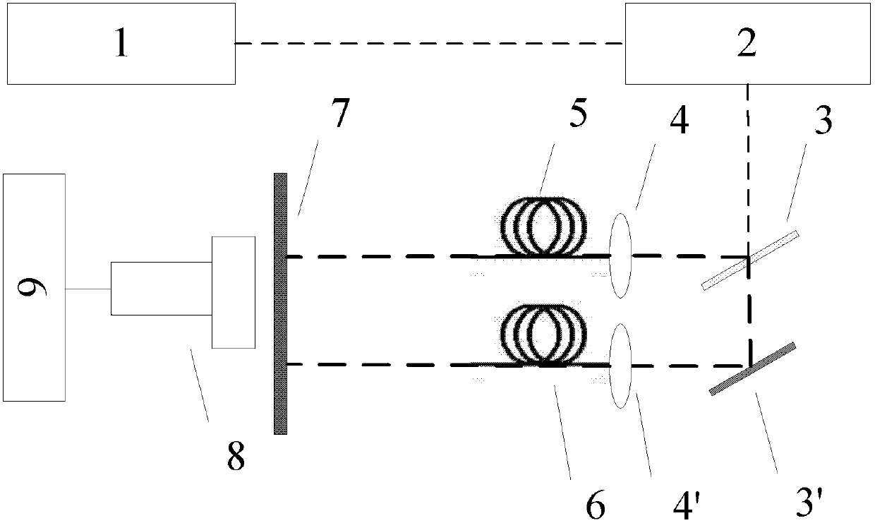
[0017] see figure 1 As shown, a kind of fluorescence lifetime imaging device based on optical delay of the present invention comprises:
[0018] A laser 1, the laser 1 is a short-pulse nanosecond or picosecond laser, the wavelength range of the laser 1 matches the excitation wavelength of the target molecule (autofluorescent substance or exogenous fluorescent substance) in the biological tissue to be measured;
[0019] A sample stage 2, the sample stage 2 is located on the optical path of the laser 1, and the biological tissue to be tested is placed;
[0020] A beam splitter 3, the beam splitter 3 is located on the light-emitting optical path of the sample stage 2, the beam splitter 3 is a multi-stage beam splitter, and the fluorescence signal is divided into N (N in this embodiment) through the multi-stage beam splitter =2) beam, each beam of optical signal enters the optical fiber imaging bundle of N bundles of different lengths through the following reflectors and coupling...
Embodiment 2
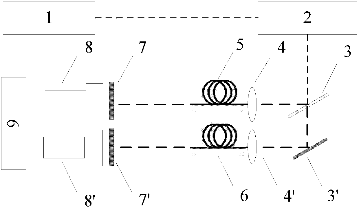
[0032] see figure 2 As shown, this embodiment is basically the same as the first embodiment, the difference is that the number of the narrowband filter 7 is two, including the narrowband filter 7 and the narrowband filter 7', which are respectively located at the first An optical fiber imaging bundle 5 and a second optical fiber imaging bundle 6 are on the optical path.
[0033] The number of the image intensifying CCD8 is two, including an image intensifying CCD8 and an image intensifying CCD8', which are located on the side of the two narrowband filters 7 away from the first optical fiber imaging bundle 5 and the second optical fiber imaging bundle 6 respectively.
PUM
 Abstract
Description
Claims
Application Information
 - R&D
- Intellectual Property
- Life Sciences
- Materials
- Tech Scout
- Unparalleled Data Quality
- Higher Quality Content
- 60% Fewer Hallucinations
Browse by: Latest US Patents, China's latest patents, Technical Efficacy Thesaurus, Application Domain, Technology Topic, Popular Technical Reports.
© 2025 PatSnap. All rights reserved.Legal|Privacy policy|Modern Slavery Act Transparency Statement|Sitemap|About US| Contact US: help@patsnap.com


