

Cutting machine
A cutting machine and frame technology, which is used in grinding machines, metal processing equipment, grinding/polishing equipment, etc., can solve the problems of poor cutting accuracy and large wear of grinding wheels, and achieve the effect of avoiding frequent and non-uniformity.
- Summary
- Abstract
- Description
- Claims
- Application Information
AI Technical Summary
Problems solved by technology
Method used
Image

Examples
Embodiment Construction
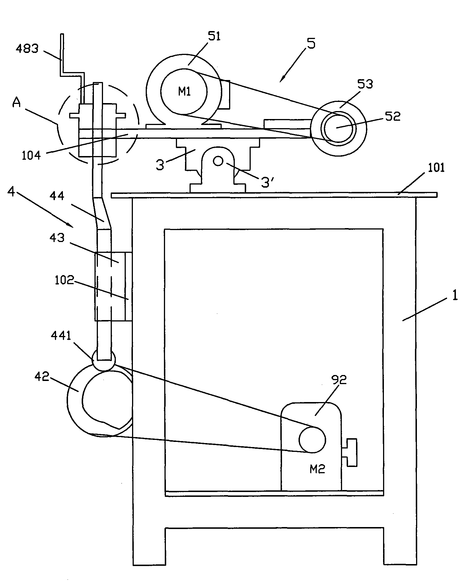
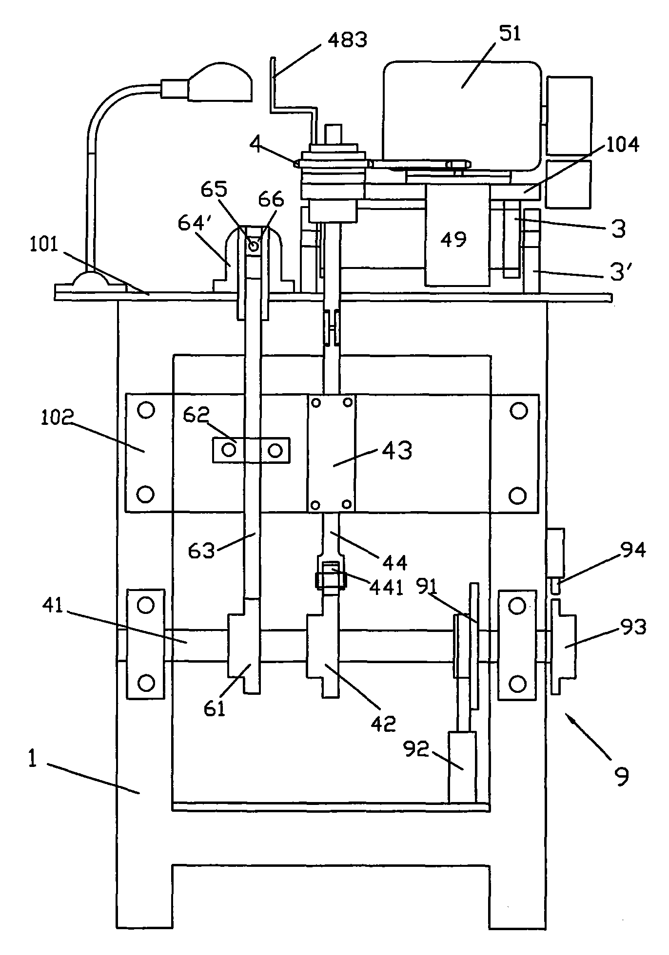
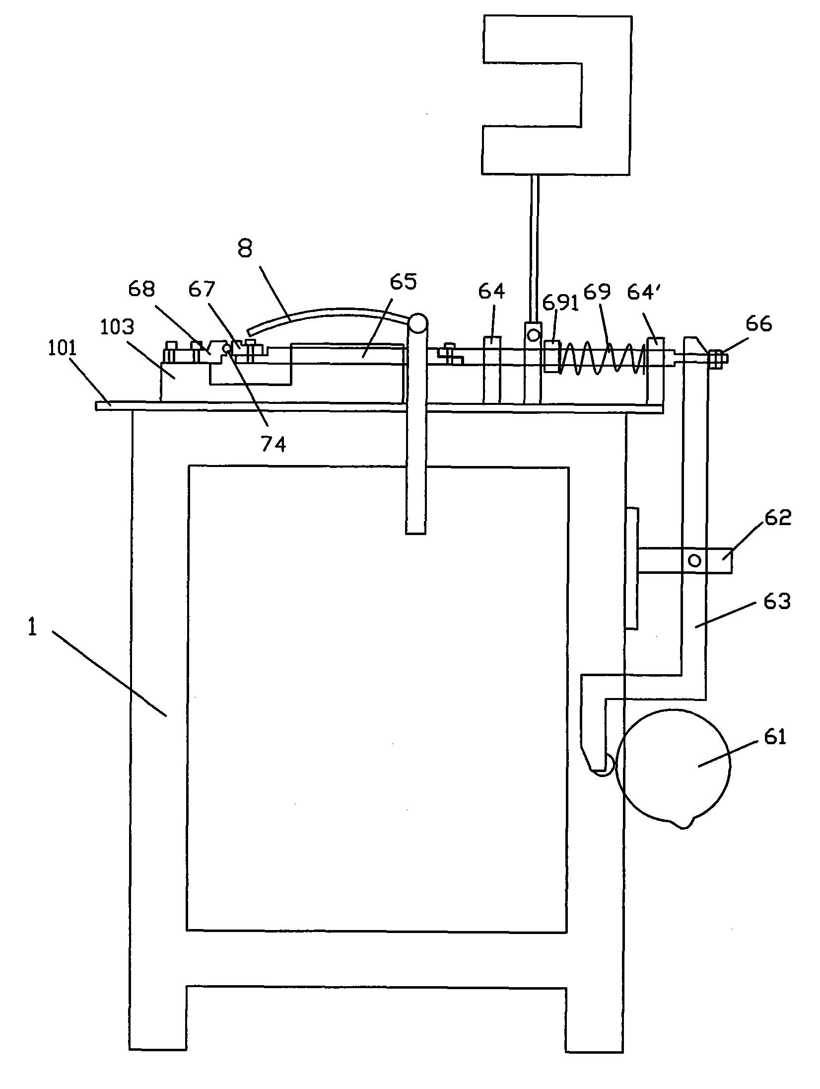
[0026] see Figure 1 to Figure 7 , the cutting machine of the present invention, it comprises, frame 1, establishes a worktable 101 on it, and rear side is provided with a fixed panel 102; Workbench 101 is provided with a clamping seat 103; Upper and lower support 3,3' , the two are pivotally connected, the lower support 3' is fixed on the workbench 101; the upper panel 104 is connected to the upper support 3;
[0027] The depth adjustment mechanism 4 includes, the driving shaft 41 is arranged on the frame 1, and an eccentric wheel 42 is sleeved on it; the ejector rod seat 43 is fixed on the fixed panel 102 of the frame 1; In the rod seat 43, the lower end of the ejector rod 44 abuts against the eccentric wheel 42 on the drive shaft 41 through a roller 441; the support 45 is connected to the upper panel 104; Bearings 451, 452; the upper end of the push rod 44 is inserted in the shaft sleeve 46, and threaded with it; the sprocket 47 and the sprocket seat 48 are arranged on the...
PUM
 Abstract
Description
Claims
Application Information