Optical fiber cleaver

A cutting device and optical fiber technology, which is applied in the coupling of optical waveguide, metal processing equipment, metal processing, etc., can solve the problems of inaccurate optical fiber cross section, inconvenient operation of optical fiber cutting device, and inability to reliably clamp optical fiber, etc., to achieve extended The effect of longevity

Inactive Publication Date: 2011-08-17
ILSIN TECH CO LTD
View PDF2 Cites 12 Cited by
  • Summary
  • Abstract
  • Description
  • Claims
  • Application Information

AI Technical Summary

Problems solved by technology

Therefore, its disadvantage is that the operation of the fiber cutting device is very inconvenient
[0009] In addition, the disadvantage of this conventional technique proposed by the applicant is that the optical fiber cannot be reliably clamped, so that the cross-section of the optical fiber is cut inaccurately.

Method used


Image

  • Optical fiber cleaver
  • Optical fiber cleaver
  • Optical fiber cleaver

Examples


Embodiment Construction

[0033] Preferred embodiments of the present invention will be described in detail below with reference to the accompanying drawings.

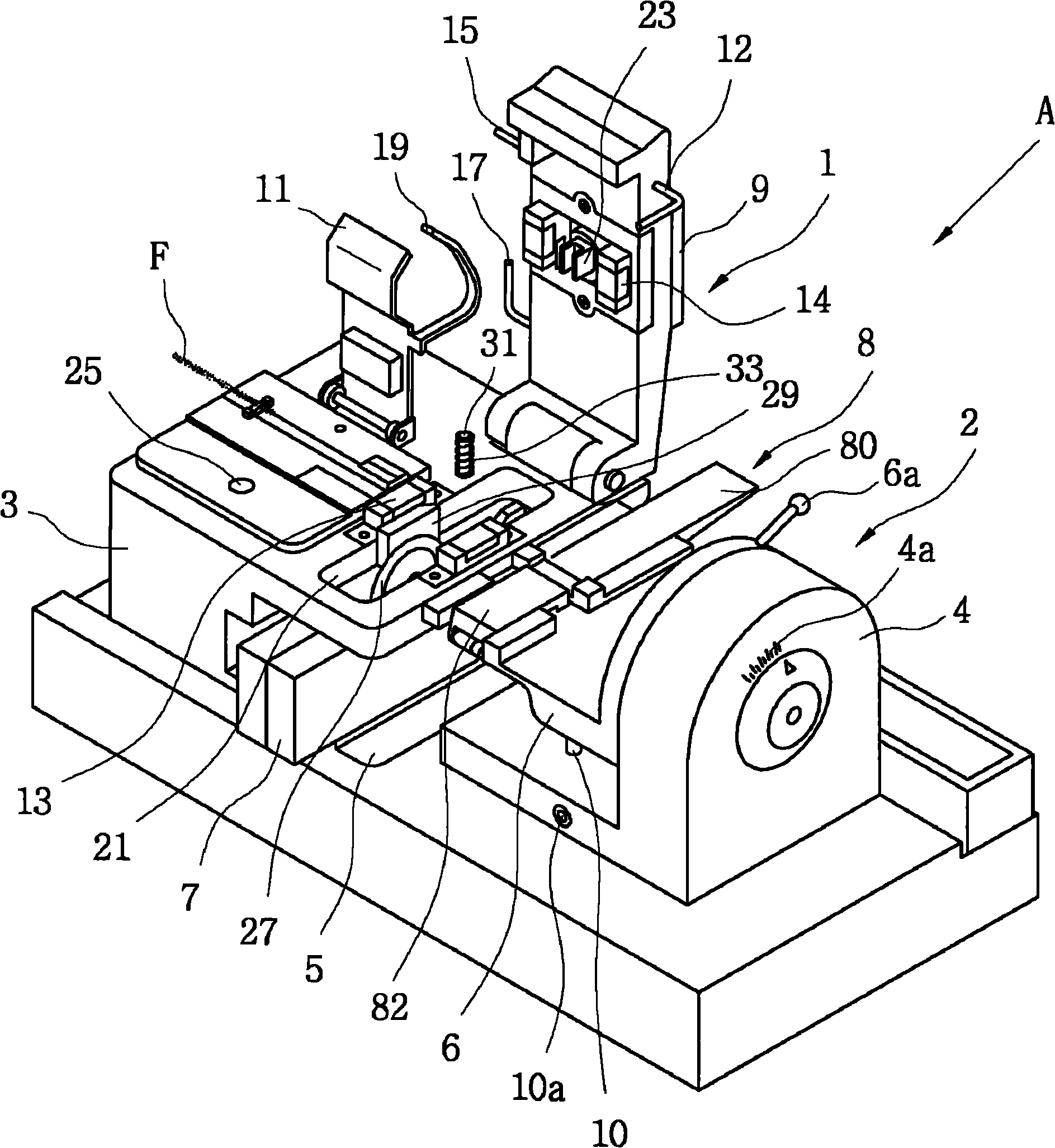
[0034] see figure 1 , The optical fiber cutting device according to the first embodiment of the present invention includes a cutting unit 1 for cutting an optical fiber F and a twisting unit 2 disposed opposite to the cutting unit 1 .

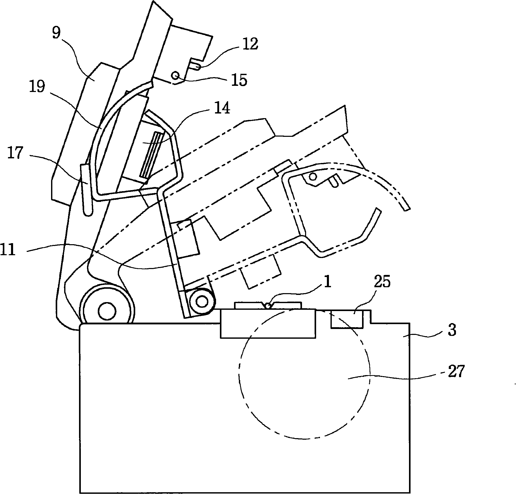
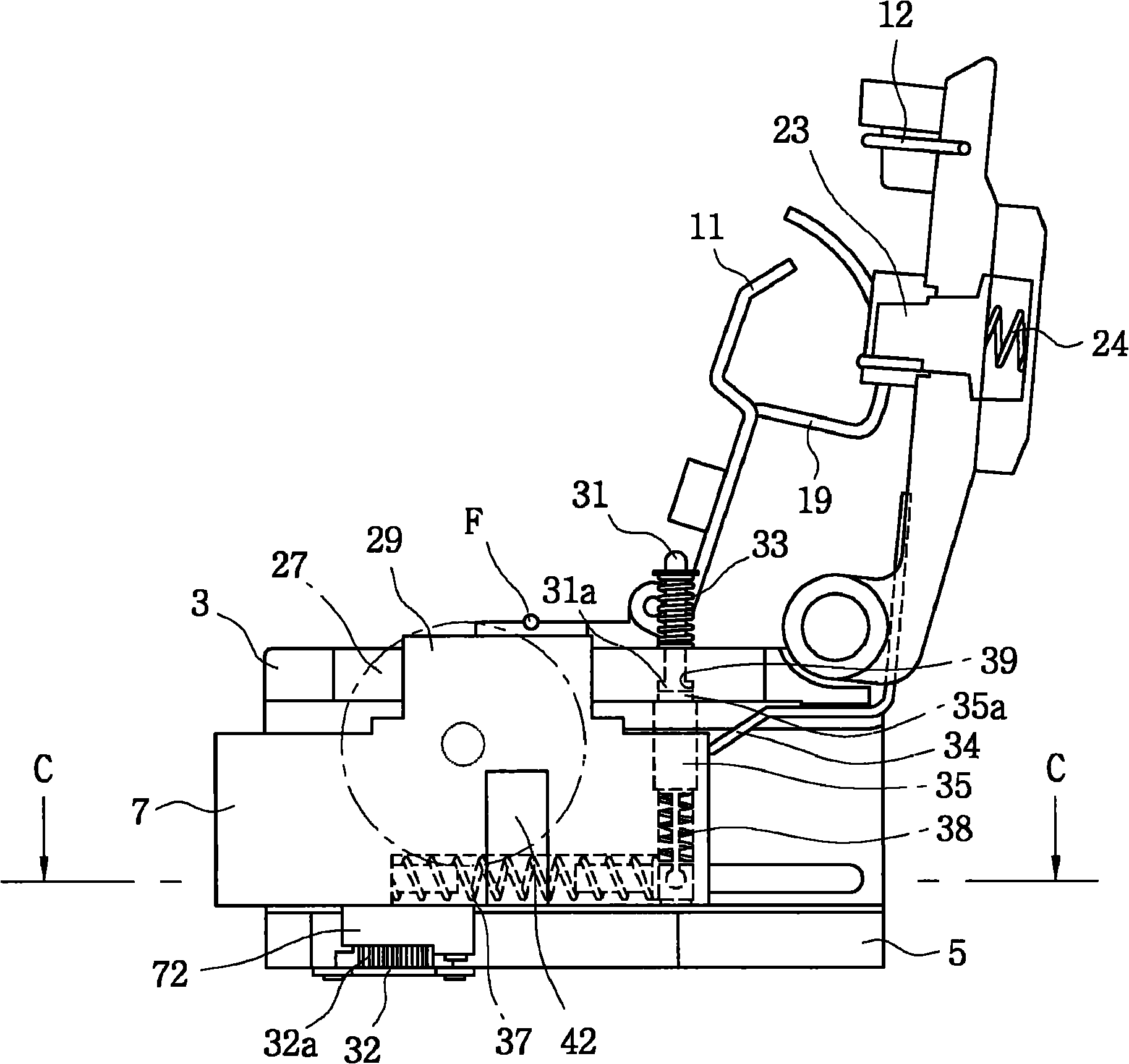
[0035] The cutting unit 1 includes a main body 3 , first and second covers 9 and 11 pivotally mounted on the main body 3 , and a slider 7 provided at one end of the main body 3 so as to be movable on a base 5 .

[0036] The main body 3 has a support 13 , an opening 21 , a magnet 25 and a protruding pin 31 on its upper surface.

[0037] The first cover 9 has a striking member 23 and a clamping block 14 on one surface thereof, and a driving lever 12, a pulling pin 15 and a pushing pin 17 on the opposite side wall thereof.

[0038] The second cover 11 has an arcuate arm 19 on its edge adjacent to the first cover ...


PUM


Abstract

An optical fiber cleaver is disclosed. The optical fiber cleaver of the invention moves a slide block (7) by the elastic force of an elastic member, and scores the optical fiber by a blade (27) in the slide block (7). The optical fiber cleaver comprises a damper (32) which is used for buffering the moving speed of slide block (7) under elastic force of the elastic member to cause the moving speed of the slide block (7) to approach a constant speed.

Description

[0001] This application is a divisional application, the application number of the original application is "200780040005.5", the application date is June 4, 2007, and the title of the invention is "optical fiber cutting device". technical field [0002] The invention relates to an optical fiber cutting device for cutting optical fibers. Background technique [0003] As is well known to those skilled in the art, an optical fiber is a fiber waveguide that uses light to transmit data. Typically, optical fibers are used in the form of cables in which several strands are combined to form a bundle. [0004] A fiber cleavage device used to cleave such an optical fiber includes two covers for holding two parts of the optical fiber, and a slider equipped with a blade for scoring the lower surface of the optical fiber. The configuration of the fiber cutting device allows the blade to score on the fiber without generating vibrations. [0005] In the process of cleaving the optical fi...

Claims


Application Information

Patent Timeline
Patent Type & Authority Applications(China)
IPC IPC(8): B26D1/00B26D7/01B26D7/26G02B6/25C03B37/16
CPCG02B6/25Y10T225/321
Inventor 宋在燮全相彻徐英培
Owner ILSIN TECH CO LTD
Why Eureka
Try Eureka