Shaft work piece clamping device

A workpiece clamp and shaft technology, applied in positioning devices, metal processing machinery parts, clamping and other directions, can solve the problems of chuck wear, difficult disassembly, heavy weight, etc., to achieve large force increase, convenient disassembly and assembly, and production cost low effect

Inactive Publication Date: 2015-03-18
XIAN ZHIYUE ELECTROMECHANICAL TECH
View PDF0 Cites 15 Cited by
  • Summary
  • Abstract
  • Description
  • Claims
  • Application Information

AI Technical Summary

Problems solved by technology

Under the guide part of the three jaws on the three-jaw chuck, there are threads that mesh with the plane threads on the back of the bevel gear. When the small bevel gear is turned with a wrench through the square hole, the bevel gear rotates, and the plane threads on the back simultaneously Drive the three jaws to approach or withdraw from the c

Method used


Image

  • Shaft work piece clamping device
  • Shaft work piece clamping device

Examples


Embodiment Construction

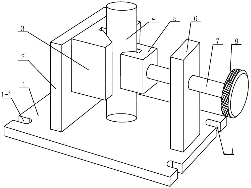
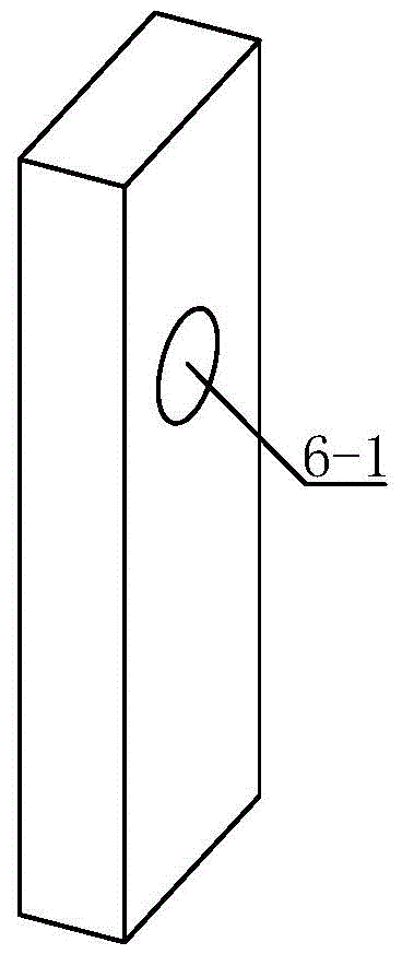
[0022] Such as figure 1 with figure 2 A shaft workpiece clamping device shown includes a rectangular bottom plate 1, the side wall of the rectangular bottom plate 1 is provided with a plurality of installation grooves 1-1, and a baffle plate 2 is welded on the upper side of the rectangular bottom plate 1, and the baffle plate 1 The right side of the plate 2 is fixed with a V-shaped pad 3 for supporting the shaft workpiece 4, and the upper side of the rectangular bottom plate 1 is welded with a support plate 6 parallel to the baffle plate 2, and the support plate 6 is provided with threads Hole 6-1, the threaded hole 6-1 is provided with a screw 7 that cooperates with it to form a threaded pair, the left end of the screw 7 is hinged with a V-shaped pressure block 5 for pressing the shaft workpiece 4, and the right end of the screw 7 A rotary handle 8 is fixedly installed, and the outer contour surface of the rotary handle 8 is provided with knurling for anti-slip.

[0023] T...


PUM


Abstract

The invention discloses a shaft work piece clamping device. The shaft work piece clamping device comprises a rectangular bottom plate, wherein a plurality of installation grooves are formed in the side wall of the rectangular bottom plate, a baffle is fixedly arranged on the upper side of the rectangular bottom plate, a V-shaped cushion block used to support a shaft work piece is fixedly arranged on the right side of the baffle, a support plate parallel to the baffle is fixedly arranged on the upper side of the rectangular bottom plate, a threaded hole is formed in the support plate, a threaded rod matched with the support plate so as to form a thread pair is arranged in the threaded hole, a V-shaped press block used to tightly press the shaft work piece is hinged with the left end of the threaded rod, and a rotatable handle is fixedly installed at the right end of the threaded rod. The shaft work piece clamping device has the advantages of being reasonable in design, reliable in work piece clamping, large in increase force, unrestricted in stroke, simple in structure, convenient and quick to disassemble and assemble, convenient to carry, long in use life, wide in application range, low in production cost, and convenient to popularize and use.

Description

technical field [0001] The invention belongs to the technical field of mechanical processing, and relates to a clamping device, in particular to a shaft workpiece clamping device. Background technique [0002] At present, in the machining process of shaft workpieces, the most commonly used clamping tool is a three-jaw chuck because the outer contour of the shaft workpiece has a certain radian. The three-jaw chuck is composed of a chuck body, movable jaws and a jaw driving mechanism. Under the guide part of the three claws on the three-jaw chuck, there are threads that mesh with the plane threads on the back of the bevel gear. When the small bevel gear is turned with a wrench through the square hole, the bevel gear rotates, and the plane threads on the back simultaneously Drive the three jaws to approach or withdraw from the center to clamp workpieces with different diameters. However, if the three-jaw chuck is used for a long time, the chuck will wear out, and the three jaw...

Claims


Application Information

Patent Timeline
IPC IPC(8): B23Q3/06
CPCB23Q3/062
Inventor 黄冰
Owner XIAN ZHIYUE ELECTROMECHANICAL TECH
Why Eureka
Try Eureka