Back pull type cylinder clamp and planet carrier machining equipment

A collet and collet technology, used in metal processing equipment, measuring/indicating equipment, metal processing machinery parts, etc., can solve the problems of poor alignment accuracy, poor axial positioning, easy entry of impurities, etc., and achieve high precision , Easy to disassemble, increase the effect of friction

Active Publication Date: 2016-07-27
杭州太普机械科技有限公司
View PDF11 Cites 15 Cited by
  • Summary
  • Abstract
  • Description
  • Claims
  • Application Information

AI Technical Summary

Problems solved by technology

[0003] There are two kinds of clamping methods for common parts processing. One is the three-jaw chuck, which has poor centering accuracy. The other is the fron

Method used


Image

  • Back pull type cylinder clamp and planet carrier machining equipment
  • Back pull type cylinder clamp and planet carrier machining equipment
  • Back pull type cylinder clamp and planet carrier machining equipment

Examples


Embodiment 1

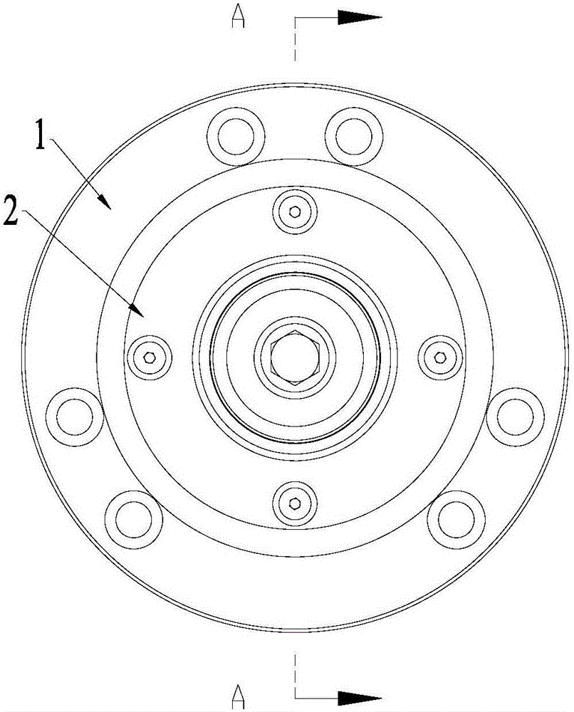
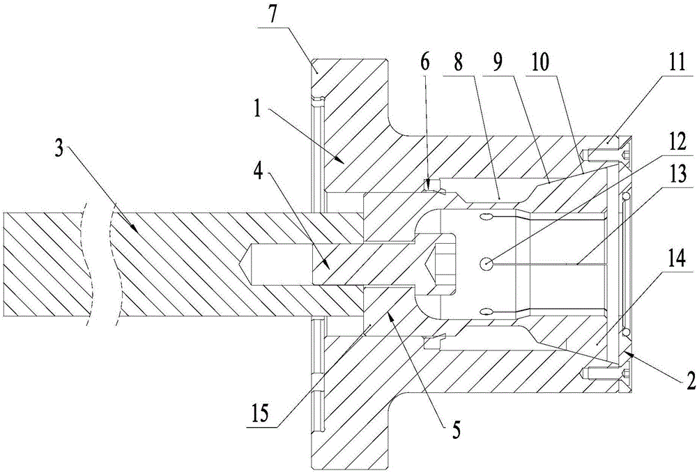
[0056] Such as figure 1 , 2 and 4, a pull-back collet comprising:

[0057] Hollow chuck seat 1, one end of the chuck seat is a fixed end 7, the other end is a mating end 11, and the inner side wall of the chuck seat includes a tapered side wall 10 at the mating end;

[0058] The hollow collet 5 is set inside the collet seat 1 and is slidably matched with the collet seat. The collet 5 includes a connecting end 15 and a clamping end 14 for clamping the workpiece. The outer wall 9 of the clamping end is a cone shape, the outer wall 9 of the clamping end cooperates with the tapered side wall 10 of the chuck seat, and the side wall of the clamping end is provided with a plurality of slits 13 in the axial direction, and each slit is evenly distributed around the axis of the chuck;

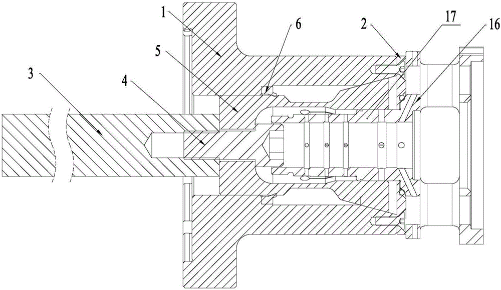
[0059] The pull rod 3 is fixed to the connecting end 5 of the chuck through the fastener 4, and the pull rod is used to drive the chuck to move along the axis of the chuck seat, so that the clamping en...

Embodiment 2

[0072] This embodiment discloses a rear pull type collet, such as Figure 9 As shown, the difference between this embodiment and Embodiment 1 is that the collet includes a detachable connecting part 24 and a clamping part 25, the connecting end is located at the connecting part, the clamping end is located at the clamping part, and the connecting part and the clamping part The thread fits, and the connecting part and the clamping part have mating surfaces that fit against each other, and at least one mating surface has a concave-convex pattern 26 .

[0073] The detachable matching method of this embodiment can realize the replacement of clamping parts of different specifications, so as to adapt to workpieces of different sizes, and when the clamping part is damaged, only the clamping part needs to be replaced, and the connecting part does not need to be scrapped. The detachable fit can save costs; the connecting part and the clamping part are threaded and at least one mating s...

Embodiment 3

[0075] This embodiment discloses a rear pull type collet, such as Figure 10 and 11 As shown, the difference between this embodiment and Embodiment 1 is that the inner wall of the elastic part 27 (each slit 13 divides the clamping end into several elastic parts 27) has a mounting groove 29, and the rear pull collet also includes a The clamping block 28 on the mounting groove, the clamping block 28 is magnetically attracted to the mounting groove 29, and one end of the clamping block 28 passes through the mounting groove. The quick installation of the clamping block can be realized through magnetic attraction, and by changing the clamping block of different sizes (the distance between the clamping block and the installation groove is different), the clamping range of the chuck can be changed, so that it can adapt to workpieces of different sizes; In actual use, at least one of the mounting groove and the clamping block has a magnetic medium, so that the two can be magnetically...


PUM


Abstract

The invention discloses a back pull type cylinder clamp. The back pull type cylinder clamp comprises a hollow chuck base, a hollow chuck, a pull rod and a first dust stop ring, wherein the inner side wall of the chuck base includes a conical side wall; the chuck is slidingly sleeved in the chuck base, and includes a connecting end and a clamping end; the outer side wall of the clamping end is conical, and is matched with the conical side wall of the chuck base; multiple gaps are axially formed in the side wall of the clamping end; the pull rod is fixed with the connecting end of the chuck for driving the chuck to move in the axis direction of the chuck base, so that the clamping end clamps or releases a workpiece; and the first dust stop ring is fixed on the end surface of a matching end of the chuck base. The outer side wall of the clamping end is conical, and is matched with the conical side wall of the matching end, so that the radial precision can be guaranteed; the chuck is backwards pulled by the pull rod to clamp the workpiece; and because of backward pulling, the workpiece can be driven to move during clamping, and the workpiece is tightly butted against the chuck base or the first dust stop ring to realize reliable axial positioning.

Description

technical field [0001] The invention relates to mechanical processing equipment, in particular to back-pull collet and planet carrier processing equipment. Background technique [0002] Planetary carriers are commonly used in transmissions and their transmission mechanisms and play an important role. With the continuous improvement of vibration, noise and transmission accuracy, the requirements for the design and processing of planetary carriers are also getting higher and higher. [0003] There are two kinds of clamping methods for common parts processing. One is the three-jaw chuck, which has poor centering accuracy. The other is the push-forward collet, which has good centering accuracy, but poor axial positioning, easy to enter impurities, and more troublesome to disassemble. Contents of the invention [0004] Aiming at the above problems, the present invention overcomes at least one deficiency, and proposes a back-pull collet and planetary frame processing equipment,...

Claims


Application Information

Patent Timeline
IPC IPC(8): B23Q3/12B23Q11/08B23Q17/00
CPCB23Q3/12B23Q11/08B23Q17/005
Inventor 蔡宁
Owner 杭州太普机械科技有限公司
Why Eureka
Try Eureka