Semi-automatic clamp for lathe

A semi-automatic fixture technology, applied in the direction of clamping, manufacturing tools, metal processing machinery parts, etc., can solve the problems of low clamping efficiency and inconvenient operation for operators, so as to reduce work intensity, improve processing efficiency, clamp reliable effect

Inactive Publication Date: 2012-10-03
NORTHWESTERN POLYTECHNICAL UNIV
View PDF7 Cites 15 Cited by
  • Summary
  • Abstract
  • Description
  • Claims
  • Application Information

AI Technical Summary

Problems solved by technology

The fixture adopts single-piece manual clamping, the clamping effi

Method used


Image

  • Semi-automatic clamp for lathe
  • Semi-automatic clamp for lathe
  • Semi-automatic clamp for lathe

Examples


Embodiment Construction

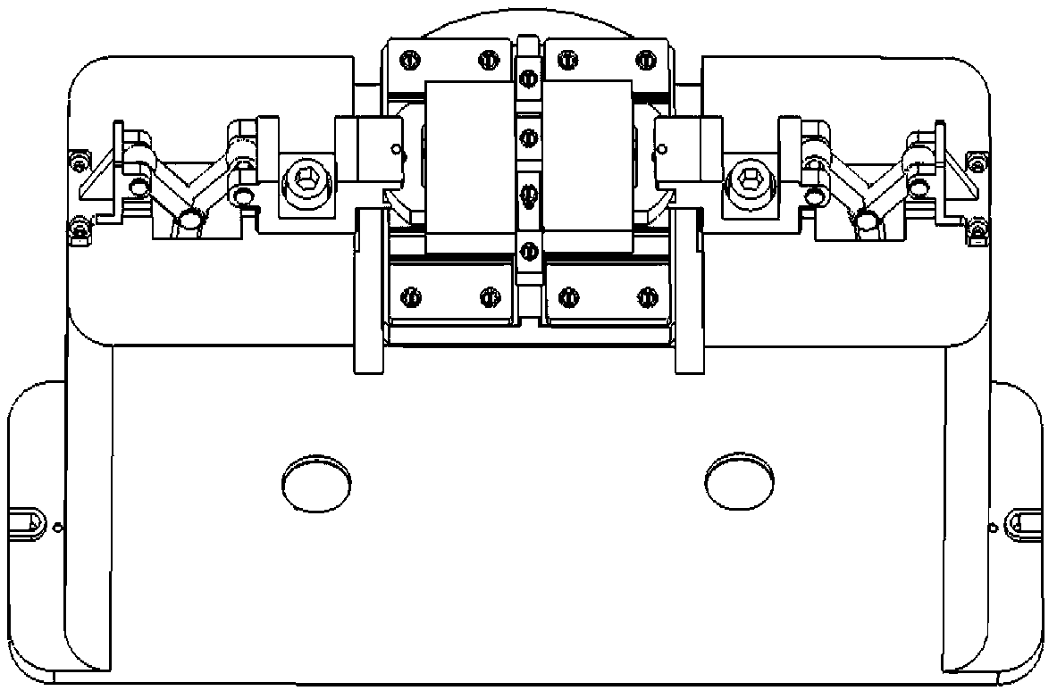
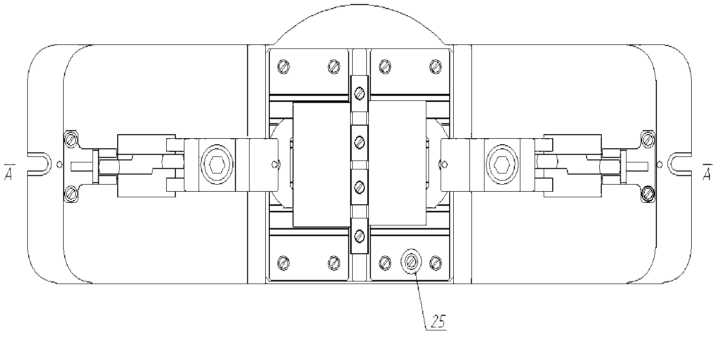
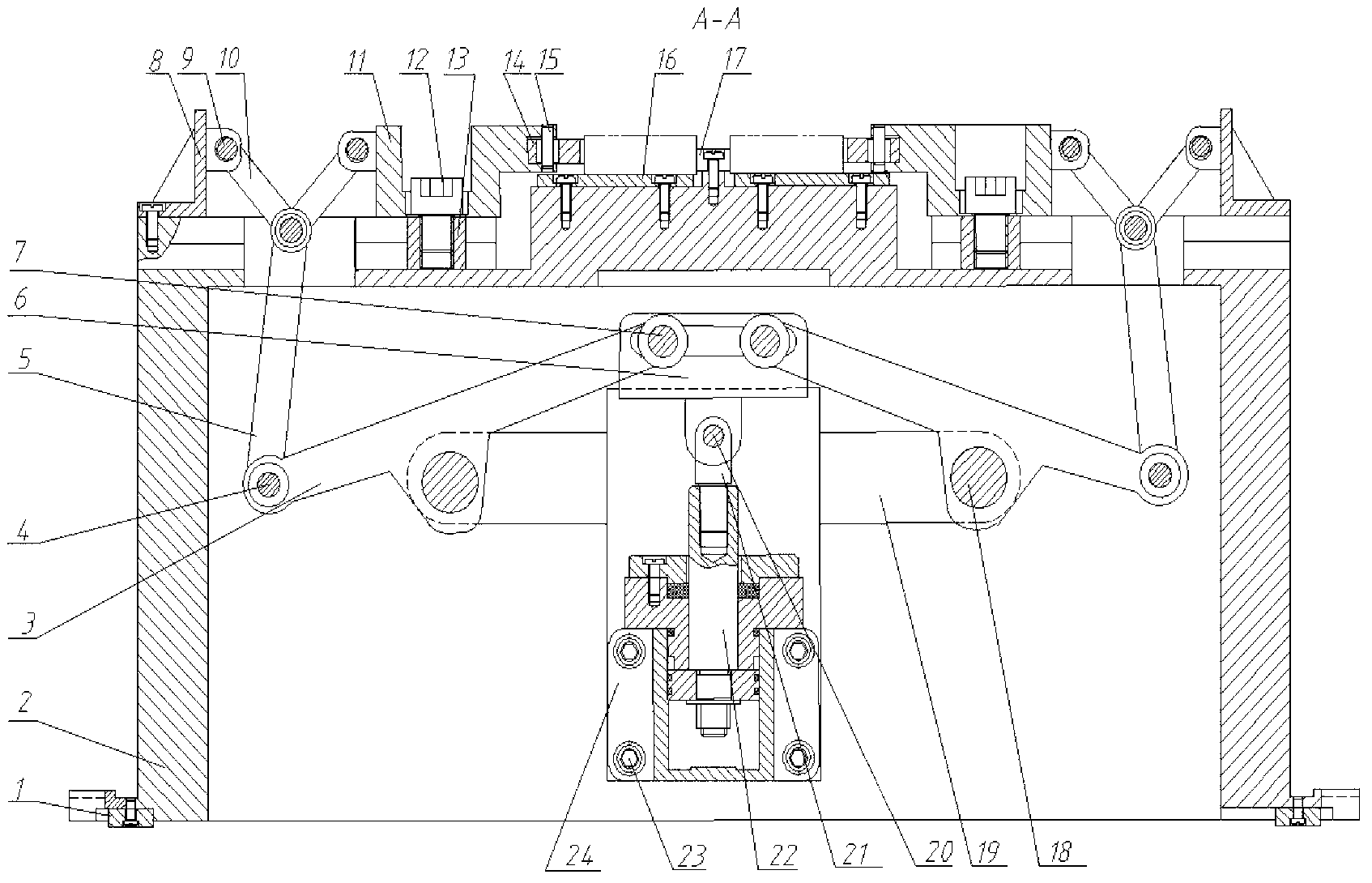
[0023] This embodiment is a semi-automatic fixture for machine tools. The fixture can clamp multiple workpieces at the same time, automatically clamps, and has a large clamping range, which can not only improve processing efficiency, but also reduce the work intensity of operators.

[0024] refer to figure 1 , figure 2 , image 3 , Figure 5 , the present invention takes the clip body as the main support mechanism, including positioning key 1, clip body 2, rotating rod 3, short shaft 4, intermediate connecting rod 5, connecting rod sliding seat 6, sliding shaft 7, connecting rod support 8, long Shaft 9, push rod 10, sliding seat 11, hexagon socket head cap screw 12, T-shaped slider 13, arc-shaped pressing block 14, pin 15, positioning plate 16, positioning block 17, supporting shaft 18, supporting rod 19, hinge shaft 20 , threaded connecting rod 21, piston rod 22, screw 23, foot type hydraulic cylinder 24, tool setting block 25, hydraulic cylinder seat 26; clamp body 2 is...


PUM


Abstract

The invention discloses a semi-automatic clamp for a lathe. Connecting rod supports are fixedly connected with two ends of a clamp body; a positioning block is mounted in the middle of the clamp body; positioning flat plates are fixed on the two sides of the positioning block; a slide seat and an arc briquette are arranged at the two ends of the positioning block; a foot margin type hydraulic cylinder is fixedly mounted on a hydraulic cylinder seat in the clamp body; connecting rod slide seat is arranged at the top of the hydraulic cylinder seat; supporting rods are arranged on two sides of the hydraulic cylinder seat; a piston rod of the hydraulic cylinder is hinged with a lug of the connecting rod slide seat through a threaded connecting rod; two rotary rods are connected with the supporting rods arranged on the two sides of the hydraulic cylinder seat; one end of each rotary rod is fixedly connected to the connecting rod slide seat; the other ends of the rotary rods are connected with middle connecting rods respectively; the middle connecting rods are respectively connected with push rods; and each of the push rods is fixedly connected with the connecting rod support at the two ends of the clamp body and the slide seat respectively. The clamp has the advantages of compact structure, reliable clamping performance and high universality; and the clamping is reasonable and fast, and a plurality of workpieces can be processed at the same time, which can not only improve the processing efficiency, but also relieve the work intensity of operators.

Description

technical field [0001] The invention relates to a fixture, in particular to a semi-automatic fixture for machine tools. It belongs to the technical field of mechanical design and tooling equipment. Background technique [0002] At present, in the mechanical processing industry at home and abroad, computer-aided fixture design (CAFD) is continuously applied to product process equipment and fixture design. It not only overcomes the shortcomings of traditional fixture design, reduces the labor intensity of designers, but also improves Quality of fixture design. Scholars at home and abroad have carried out a lot of research on CAFD technology. For example, using SolidWorks software as a platform, first establish a parametric solid model library for standard parts of fixtures, and then develop non-standard solid model libraries for different fixtures. After the three-dimensional solid model of the assembly is obtained through virtual assembly, the two-dimensional engineering dr...

Claims


Application Information

Patent Timeline
IPC IPC(8): B23Q3/00
Inventor 张艳飞李晓莹李光涛赵小军肖同新
Owner NORTHWESTERN POLYTECHNICAL UNIV
Why Eureka
Try Eureka