Eureka AIR delivers breakthrough ideas for toughest innovation challenges, trusted by R&D personnel around the world.

Drawer

A technology for drawers and connectors, which is applied to drawers, furniture parts, household appliances, etc., which can solve the problems of many assembly steps, exposed adjustment devices, and unsightly appearance, and achieve the effects of low production cost, simple assembly, and reasonable structure

Active Publication Date: 2012-04-11
伍志勇
View PDF8 Cites 9 Cited by
  • Summary
  • Abstract
  • Description
  • Claims
  • Application Information

AI Technical Summary

Problems solved by technology

The structure of the adjustment device is relatively complicated, there are many assembly steps, and the volume is large. After the assembly is completed, the adjustment device is exposed, which is not beautiful and cannot meet the aesthetic requirements of consumers.

Method used


Image

  • Drawer
  • Drawer
  • Drawer

Examples


no. 1 example

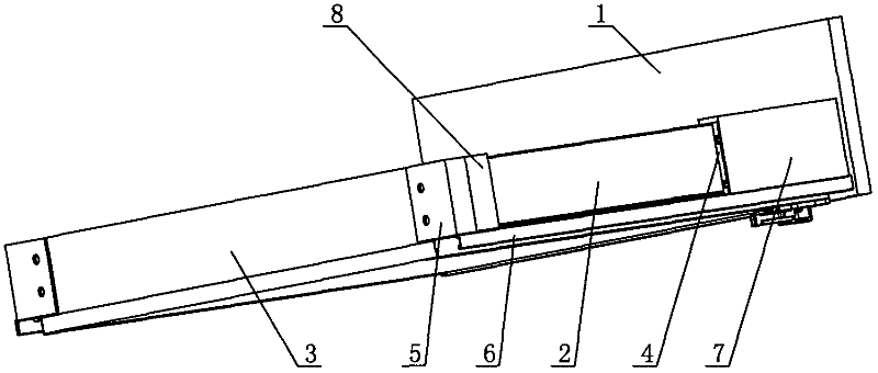
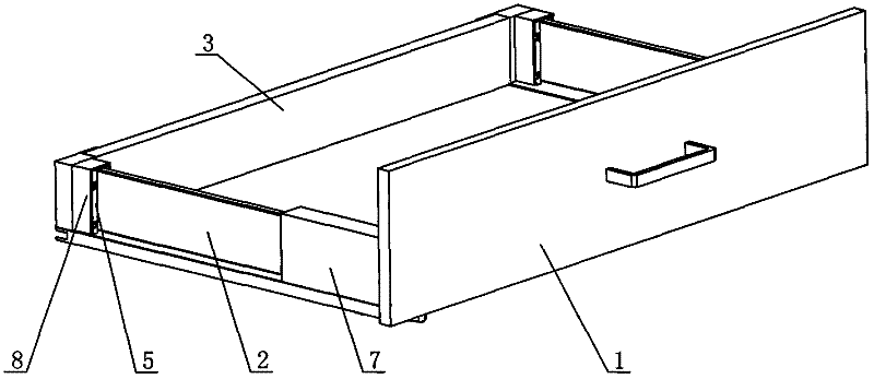
[0033] see Figure 1-Figure 11 , the drawer includes a drawer panel 1 connected to the front connector 4, a drawer rear panel 3 connected to the rear connector 5, and the drawer side panel 1 is inserted between the front and rear connectors, and the front connector 4 Outer covers that can cover the drawer side panels 1 are respectively arranged on the and rear connecting parts 5 , and the two outer covers cover the front connecting part 4 and the rear connecting part 5 respectively.

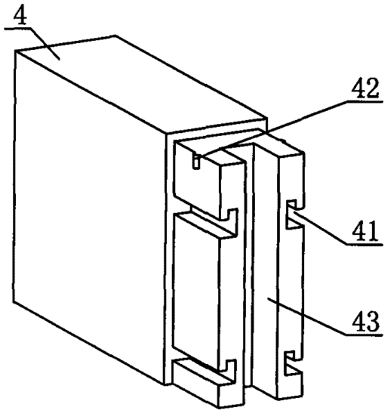
[0034] see Figure 1-Figure 5 , the end of the front connector 4 is provided with an opening slot A 43 that can be inserted into the drawer side panel 1, and the outer cover A 7 is sleeved at the joint between the front connector 4 and the drawer side panel 1. In this embodiment, the outer cover A The length of 7 is suitable with front connector 4, just connects 4 before covering when drawer side plate 1 can be entangled. The front connector 4 is provided with four positioning slots A 41 which ...

no. 2 example

[0041] see Figure 12-Figure 16 , The main difference between this drawer and the first embodiment is that the two outer covers provided on the front connecting piece 4 and the rear connecting piece 5 partially cover the front connecting piece 4 and the rear connecting piece 5 respectively. Moreover, the structures of the two covers are the same, which is the cover C10. The outer cover C 10 is shorter than the length of the front and rear connectors, and a set of positioning buckles C 10.1 are arranged on it to buckle with the positioning groove A 41 of the front connector 4 and the positioning groove B 51 of the rear connector 4 respectively, so that Can slide into the front and rear connectors respectively, and cover the drawer panel 2. Between the front connecting piece 4, the rear connecting piece 5 and the outer cover C 10, a convex-concave limiting portion is provided, and the convex-concave limiting portion includes a limiting concave hole A 42 provided on the front co...


PUM


Abstract

The invention discloses a drawer which comprises a drawer front plate connected to a front connecting piece and a drawer rear plate connected to a rear connecting piece, wherein a drawer side plate is inserted between the front and rear connecting pieces; an outer cover capable of covering the drawer side plate is arranged on the front connecting piece and / or rear connecting piece; and the outer cover partially or completely covers the front connecting piece and / or rear connecting piece. An open groove A into which the drawer side plate can be inserted is arranged at an end part of the front connecting piece; and an outer cover A is in sleeve joint with the joint between the front connecting piece and the drawer side plate. An open groove B into which the drawer side plate can be inserted is arranged at an end part of the rear connecting piece, and an outer cover B is in sleeve joint with the joint between the rear connecting piece and the drawer side plate. The front and rear connecting pieces are fixedly connected with a drawer bottom plate respectively or fixedly connected with a support rail. In the invention, the outer cover can prevent the drawer side plate from loosening; and as the outer cover can cover the joints between the front and rear connecting pieces and the drawer side plate, the drawer appears more beautiful and conforms to the aesthetic requirements of consumers.

Description

technical field [0001] The invention relates to a drawer. Background technique [0002] I disclosed a drawer panel adjusting device in Chinese Patent Document No. CN101543348 on September 30, 2009, including an adjusting seat arranged in the drawer side plate, the drawer panel is connected with the adjusting seat through a connecting piece, and the adjusting seat is provided with The left and right adjustment blocks have slots corresponding to the connectors at one end of the left and right adjustment blocks, and the connectors are inserted into the slots and move left and right with the left and right adjustment blocks. The left and right adjustment blocks include the clips on the left and right sides and the pads arranged between the lower parts of the clips. The clips on both sides and the middle pads are integrated into one body, showing an inverted convex shape, and a U-shaped slot is formed between the upper parts of the clips. , the inner side of the slot fits with t...

Claims


Application Information

Patent Timeline
Patent Type & Authority Applications(China)
IPC IPC(8): A47B88/04
Inventor 伍志勇
Owner 伍志勇
Why Eureka
Eureka Blog
Learn More