Respiratory flow rhythm control gas valve

A technology of breathing flow and air valve control, which is applied in the direction of respirator, etc., can solve the problems that the air valve cannot be applied and cannot control the air flow rate, etc., and achieves the effect of ingenious structure and adjustment of the air flow rate.

Inactive Publication Date: 2012-04-11
于邦仲
View PDF6 Cites 3 Cited by
  • Summary
  • Abstract
  • Description
  • Claims
  • Application Information

AI Technical Summary

Problems solved by technology

However, the existing air valve usually needs to manually adjust the valve core to realize the on-off of the air flow, and the flow rate of the air flow cannot be controlled
In the medical ventilator, it is necessary to realize the on-off of the electronically controlled air flow and the

Method used


Image

  • Respiratory flow rhythm control gas valve
  • Respiratory flow rhythm control gas valve
  • Respiratory flow rhythm control gas valve

Examples


Embodiment Construction

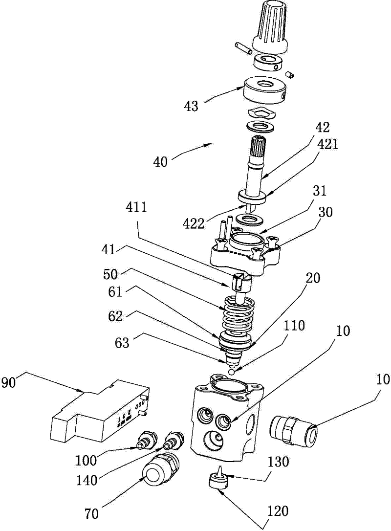
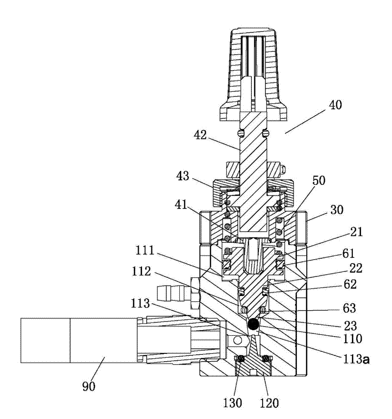
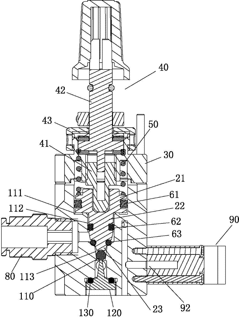
[0020] Such as Figure 1-8 Shown, a breathing flow rhythm control air valve of the present invention includes: a valve body 10 with an air chamber 11, a valve core 20 is installed in the air chamber 11, a valve cover 30 is arranged on the top of the valve body 10, the valve The cover 30 is provided with a screw mechanism 40 for adjusting the stroke size of the spool 20 up and down. The top post 41 below the screw mechanism 40 corresponds to the top of the spool 20, and a spring is connected between the spool 30 and the spool 20. 50; the spool 20 is composed of a spool head 21, a spool body 22 and a spool bottom 23 forming a T-shaped structure, an upper sealing ring 61 is set on the spool head 21, and a There is a middle sealing ring 62, and a lower sealing ring 63 is set at the bottom end 23 of the valve core, wherein the upper sealing ring 61 and the middle sealing ring 62 are in airtight sliding contact with the inner wall of the air chamber 11, and the lower sealing ring 63...


PUM


Abstract

The invention relates to a respiratory flow rhythm control gas valve which can be opened or closed by electric control and can regulate the magnitude of gas flow. In the invention, a two-position three-way electromagnetic valve is connected with a valve body to enable the gas valve to be opened or closed by electric control, and the change of the size of a ventilation gap is linearly increase through a steel ball in the gas valve and a linear inverted cone-shaped cavity, thus the travel distance between a support pillar and a valve core can be controlled through a screw mechanism so as to realize the purposes of controlling and regulating the magnitude of gas flow. By adopting the structure, the respiratory flow rhythm control gas valve has the characteristic of artful structure, can be opened or closed by electric control, can regulate the magnitude of gas flow, and is suitable for being applied in medical respirators.

Description

technical field [0001] The invention relates to the technical field of an air valve device in a medical ventilator, in particular to a breathing flow rhythm control air valve that can be switched on and off by electric control and can adjust the airflow flow. Background technique [0002] At present, the existing air valve has a relatively simple structure, which realizes the on-off of the air flow by moving the valve core up and down. However, the existing air valve usually needs to manually adjust the valve core to realize the on-off of the air flow, and the flow rate of the air flow cannot be controlled. In the medical ventilator, it is necessary to realize the on-off of the electronically controlled airflow and the size control of the airflow at any time according to the patient's condition. The existing air valve cannot be used in the medical ventilator. In view of this, how to design a Controlling the on-off of the air-flow automatically and the air valve capable of c...

Claims


Application Information

Patent Timeline
IPC IPC(8): A61M16/20
Inventor 顾志超成其新于邦仲
Owner 于邦仲
Why Eureka
Try Eureka