Vehicle lighting device supporting structure

A lighting device, vehicle technology, applied in bicycle accessories, transportation and packaging, optical signals, etc., to achieve the effect of improving appearance, simple supporting structure, and reliable support

Active Publication Date: 2013-09-04
HONDA MOTOR CO LTD
View PDF5 Cites 0 Cited by
  • Summary
  • Abstract
  • Description
  • Claims
  • Application Information

AI Technical Summary

Problems solved by technology

In addition, since the cargo support portion (21) is exposed at the front of the vehicle, there is room for improvement in the appearance of the vehicle

Method used


Image

  • Vehicle lighting device supporting structure
  • Vehicle lighting device supporting structure
  • Vehicle lighting device supporting structure

Examples


Embodiment 1

[0050] First, Embodiment 1 of the present invention will be described with reference to the drawings.

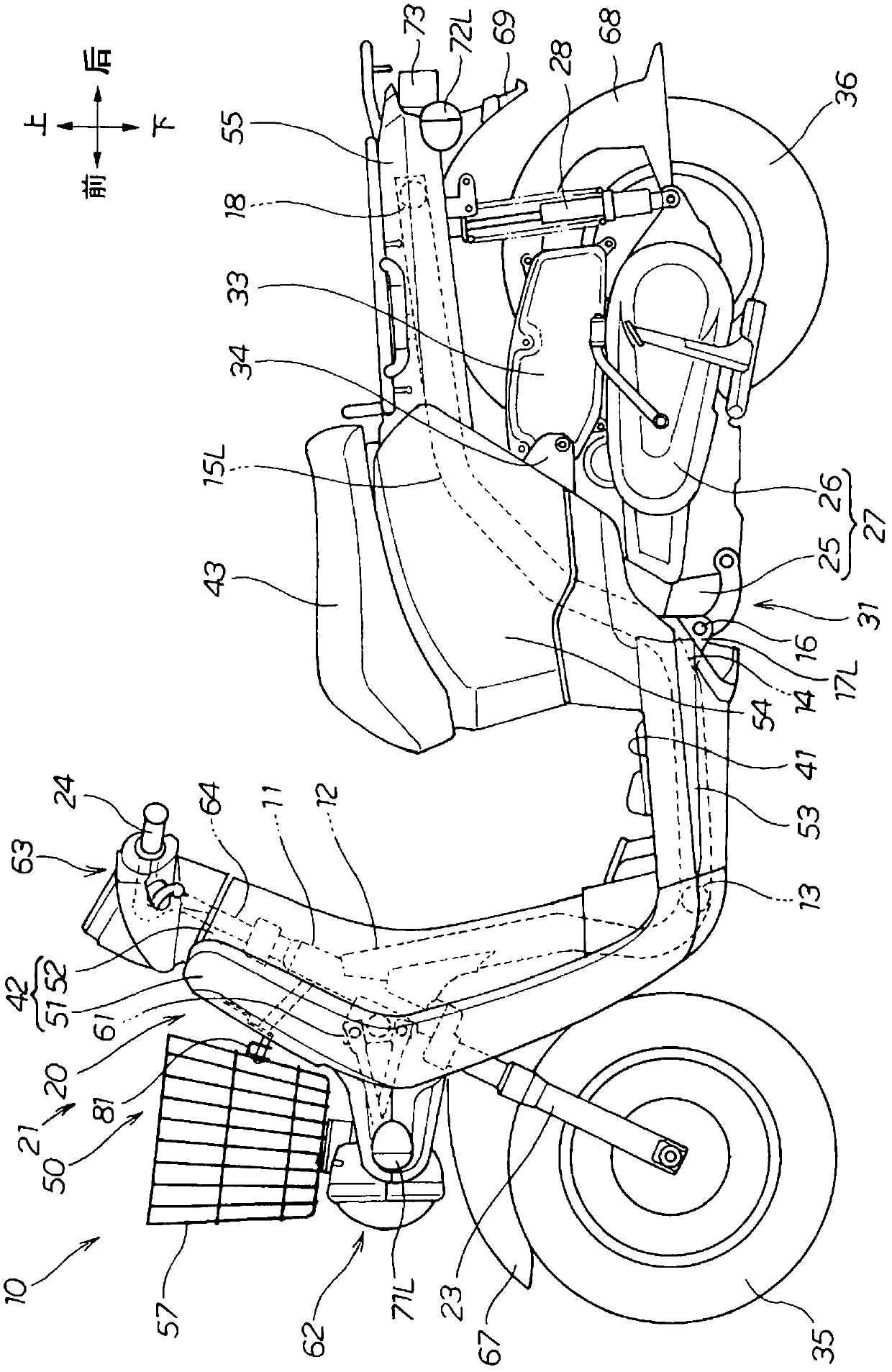
[0051] Such as figure 1 As shown, a vehicle frame 20 is provided on the motorcycle 10, and the main components of the vehicle frame 20 are: a head pipe 11, a main frame 12 extending obliquely from the head pipe 11 toward the rear, and a main frame 12 on the main frame 12. The rear end portion of the front cross frame 13 extending in the vehicle width direction extends from the head pipe 11 toward the left and right outwards in the vehicle width direction, is connected to the left and right ends of the front cross frame 13 and then extends toward the rear of the vehicle, and at the middle portion 14 toward the vehicle. The left and right side frames 15L, 15R (only the reference numeral 15L on the front side in the drawing) extending obliquely upward from the rear and extending horizontally toward the rear of the vehicle are attached to the middle part 14 and erect the pivot s...

Embodiment 2

[0132] Embodiment 2 of the present invention will be described below with reference to the drawings.

[0133] Such as Figure 13 As shown, the upper illuminator cover 86B is integrally formed with the front cover 51B. Therefore, the number of parts can be reduced as compared with the case where the upper lighting device cover and the front cover are constituted by separately formed single parts.

Embodiment 3

[0135] Embodiment 3 of the present invention will be described below with reference to the drawings.

[0136] Such as Figure 14 As shown, the front cover 51C is divided into a front cover upper half 181 and a front cover lower half 182, the front cover upper half 181 is integrated with the upper side lighting device cover 86C, and the front cover lower half 182 is connected with the lower side lighting device The cover 85C is integrally formed.

[0137] Therefore, the number of parts can be reduced as compared with the case where the front cover upper half and the upper side lighting device cover are composed of separately formed single parts.

[0138] In addition, the front cover lower half 182 is integrally formed with the lower lighting device cover 85C. Therefore, the number of parts can be reduced as compared with the case where the front cover lower half and the lower lighting device cover are composed of separately formed single parts.

[0139] In addition, in the e...


PUM


Abstract

The task of the invention is to provide a vehicle supporting structure which makes the vibration of a vehicle hard to be transmitted to a lighting device, and can improve the peripheric appearance beauty of the lighting device. The vehicle lighting device supporting structure includes a metal front supporting strip (61) which extends forward from a head tube (11) to support a cargo basket (57). An resin-made upper lighting device cover (86) covering the front supporting strip (61) and the lighting device (62) extends forward from a front cover (51). A resin-made lower lighting device cover (85) covering the front supporting strip (61) and the lighting device (62) extends forward along the vehicle width direction from the front cover (51). The lower lighting device cover (85) which is supported on the front supporting strip is used to support the lighting device (62).

Description

technical field [0001] The present invention relates to an improvement of a lighting device supporting structure of a vehicle. Background technique [0002] Vehicles are generally provided with lighting means for illuminating the front. Various schemes have been proposed for the supporting structure of the lighting device (for example, refer to Patent Document 1 ( figure 1 )). [0003] As in Patent Document 1 figure 1 As shown, a headlight (illuminating device) (20) is disposed in front of the vehicle on the leg cover (12) (numbers in parentheses indicate reference numerals described in Patent Document 1, the same below). Similarly, a cargo support portion (21) for supporting a basket (23) is arranged in front of the vehicle of the leg cover (12). [0004] The load support portion (21) is a metal member and is attached to the vehicle frame (5). A lighting device (20) is installed on the cargo supporting part (21). [0005] Therefore, the lighting device (20) is mounted...

Claims


Application Information

Patent Timeline
Patent Type & Authority Patents(China)
IPC IPC(8): B62J6/02
Inventor 横内浩平丸山智千
Owner HONDA MOTOR CO LTD
Why Eureka
Try Eureka