
Arc blowing device for low-voltage circuit breaker

A technology for low-voltage circuit breakers and arc extinguishing grids, which is applied to parts and components of circuit breakers, can solve the problems of increasing the degree of burning of lower contacts caused by arcs, and the inability to effectively change conductive components, etc., so as to reduce burning and Effect of small dwell time

Inactive Publication Date: 2012-04-25
JIANGSU PHONO ELECTRIC
View PDF6 Cites 4 Cited by
  • Summary
  • Abstract
  • Description
  • Claims
  • Application Information

AI Technical Summary

Problems solved by technology

The overall shape of the conductive components in this structure tends to be Z-shaped. When a current passes through, the middle and lower part of the Z-shaped will generate a magnetic field that prevents the arc from moving to the arc extinguishing grid, which will affect the transfer of the arc to the arc-starting parts, increasing the Burning degree of arc to lower contact
Although there is a slot in the middle of the lower part of the arc starting part, due to the limitation of shape and space, it is also unable to effectively change the magnetic field generated by the conductive component to prevent the arc from moving to the arc extinguishing grid

Method used


Image

  • Arc blowing device for low-voltage circuit breaker
  • Arc blowing device for low-voltage circuit breaker
  • Arc blowing device for low-voltage circuit breaker

Examples


Embodiment Construction

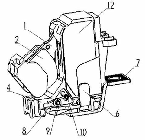
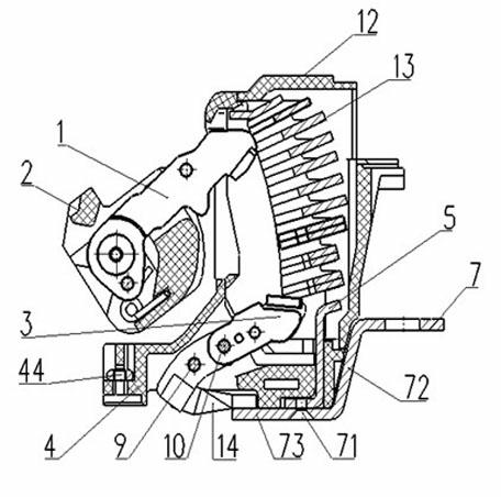
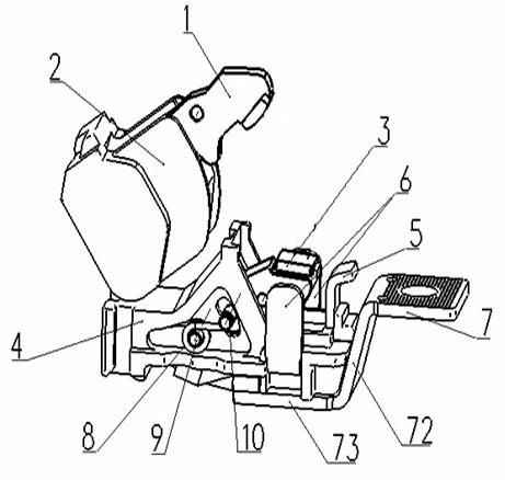
[0016] like Figure 1-3 As shown, the present invention includes an arc extinguishing chamber 12 , a moving contact 1 and a static contact 3 , the lower part of the arc extinguishing chamber 12 is a support 4 , and an arc extinguishing grid 13 is arranged in the inner cavity of the arc extinguishing chamber 12 . The front end of the moving contact 1 is a rotating end, the rotating end is connected to the rotating shaft 2, and is located outside the arc extinguishing chamber 12, the rear end of the moving contact 1 is a contact end, and the contact end extends into the inner cavity of the arc extinguishing chamber 12; The front end of the contact 3 is the connection end, which is pivotally connected to the bracket 4, and the rear end of the static contact 3 is the contact end, which extends into the inner cavity of the arc extinguishing chamber 12 and is located on the arc extinguishing grid. The lower part of sheet 13 corresponds to the contact end of moving contact 1.

[001...


PUM


Abstract

The invention discloses an arc blowing device for a low-voltage circuit breaker. A bracket is arranged at the lower part of an arc extinguishing chamber; a connecting end at the front end of a static contact can be pivotally connected with the bracket; two first grooves are respectively arranged at the left side and the right side of the rear part of the bracket; magnetism-increasing parts are arranged on the first grooves; the bottom surfaces of the magnetism-increasing parts are fixedly arranged in the first grooves; the side surfaces of the magnetism-increasing parts upwards extend to the outer part of the arc extinguishing chamber; contact ends of a movable contact and the static contact are positioned between the side surfaces of the two magnetism-increasing parts or at the positions close to the front ends of the two magnetism-increasing parts; a connecting plate is arranged at the rear part of the bracket; a magnetic conducting part is arranged between the static contact and the intermediate section of the connecting plate and is also positioned below an arc extinguishing grid plate; the upper section of the magnetic conduction part extends into the arc extinguishing chamber and is parallel to the arc extinguishing grid plate at a clearance; the contact end of the static contact is inclined; the magnetism-increasing parts can be used for enhancing an arc blowing magnetic field and increasing the repelling-open speed of the static contact; and the magnetic conducting part can be used for centralizing a magnetic filed generated by the connecting plate at the electric arc to the part, so that the stay time of the electric arc at the contact is effectively reduced and the entrance of the electric arc into the arc extinguishing device is accelerated.

Description

[0001] technical field [0002] The invention relates to a high-breaking low-voltage circuit breaker, in particular to an arc-blowing device in its contact system capable of quickly blowing and extinguishing the arc. Background technique [0003] Current limiting and arc extinguishing performance are important performance indicators of molded case circuit breakers. To improve this indicator, the key is to speed up the separation speed of moving and static contacts, lengthen the arc, transfer the arc root as soon as possible, and accelerate the arc entering the arc extinguishing grid. Existing high breaking circuit breakers use moving and static contacts to open at the same time to increase the opening distance between the contacts, so as to elongate the arc and increase the arc voltage to limit the increase of short-circuit current. However, high-breaking low-voltage circuit breakers have higher segmentation capacity and greater energy. The temperature of the arc can be as...

Claims


Application Information

Patent Timeline
Patent Type & Authority Applications(China)
IPC IPC(8): H01H73/18
Inventor 郑改红张海燕宗伟光刘乾
Owner JIANGSU PHONO ELECTRIC
Learn More