Kinematic mirror mount adjustable from two directions

A technology for kinematic, reflector applications in the field of positional devices that can address issues affecting mirror mount size, weight, and other physical properties, violations of overall profile and mechanical packaging, and proximity adjustment actuator limitations

Inactive Publication Date: 2012-04-25
EASTMAN KODAK CO
View PDF7 Cites 11 Cited by
  • Summary
  • Abstract
  • Description
  • Claims
  • Application Information

AI Technical Summary

Problems solved by technology

The need for compact packaging not only affects the size, weight, and other physical properties of the mirror mount, it can also place limitations on access to the adjustment actuator
Conventional solutions that provide access to mirror adjustment once the mirror mount is installed often violate requirements that limit the overall profile and mechanical footprint of the mirror mount

Method used


Image

  • Kinematic mirror mount adjustable from two directions
  • Kinematic mirror mount adjustable from two directions
  • Kinematic mirror mount adjustable from two directions

Examples


Embodiment Construction

[0026] The description focuses in particular on elements forming part of, or cooperating more directly with, the device according to the invention. It is to be understood that elements not specifically shown or described may take various forms well known to those skilled in the art.

[0027] The drawings shown and described herein are for illustrating principles of operation according to the present invention and may not be drawn to show actual size or scale. Due to the relative dimensions of the constituent parts of the mirror mount of the present invention, some exaggeration is necessary in order to emphasize the basic structure, shape and principles of operation.

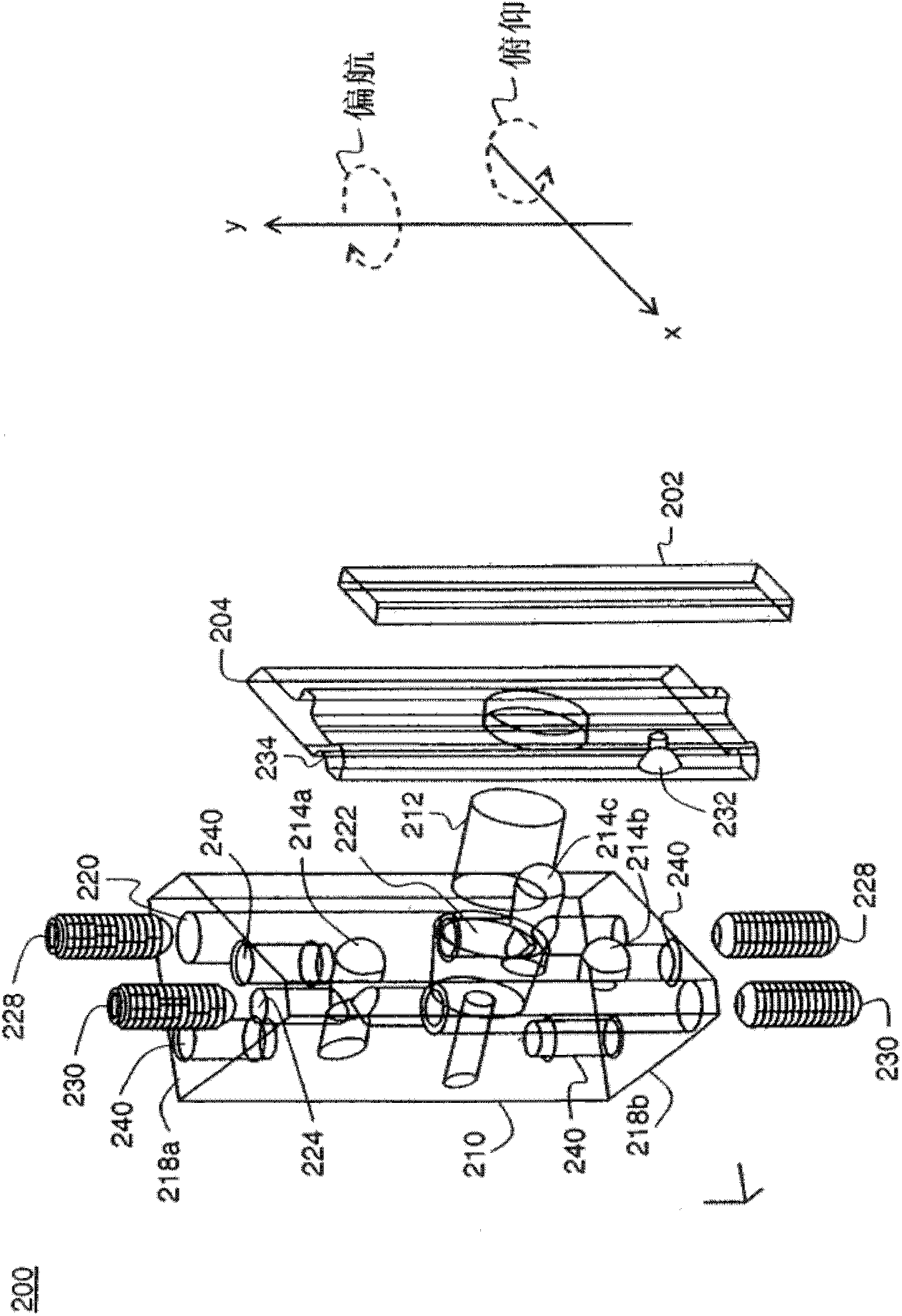
[0028] The terms "bottom" and "top" are used to refer to opposing surfaces or other features of components described and shown herein, but are not used to limit the components to a vertical orientation. One advantage of the mirror mount of the present invention relates to its adaptability of orientation in direc...


PUM


Abstract

A kinematic optical mount comprising a frame supporting an optical element,a base member having first and second surfaces and providing magnetic attraction to seat the frame against first, second, and third point contacts. The kinematic optical mount further includes threaded yaw and pitch adjustment cavities extending through the base member from the first surface to the second surface, together with threaded yaw and pitch adjustment inserts that can be inserted into the yaw and pitch adjustment cavities from either the first or second surfaces of the base member enabling adjustment of two of the point contacts from the direction of the either the first or second surfaces.

Description

technical field [0001] The present invention relates generally to an apparatus for precision mounting and positioning of components, and more particularly to an apparatus for mounting and adjusting the position of mirrors or other reflective optical elements. Background technique [0002] Proper alignment of mirrors and other types of reflective optical surfaces is of particular value in optical systems where precise redirection of light is required. This can be a particularly important requirement for systems using lasers. Without high-precision alignment, for example, small deviations in a laser beam for a measuring instrument or for an imaging device can seriously impair system performance. [0003] Conventional methods for mirror mounting and adjustment often require precision machining and complex placement of the actuators used to fine-tune the mirror position. For precise alignment of larger mirrors that can be used with higher power lasers, this method can be adapt...

Claims


Application Information

Patent Timeline
Patent Type & Authority Applications(China)
IPC IPC(8): G02B7/182G02B27/09G02B27/10H01S3/00
CPCH01S3/005G02B7/1825
Inventor M·A·哈兰德M·E·布里杰斯
Owner EASTMAN KODAK CO
Why Eureka
Try Eureka