

X-ray detector and x-ray ct scanner
An X-ray and detector technology, which is applied in the field of X-ray detectors and X-ray CT devices, can solve the problems of uneven temperature of the detection package, unsuitable for large-capacity heating, and inability to obtain temperature control capabilities, so as to eliminate adverse effects Effect
- Summary
- Abstract
- Description
- Claims
- Application Information
AI Technical Summary
Problems solved by technology
Method used
Image

Examples
no. 1 Embodiment approach
[0038] First, the first embodiment will be described.
[0039] [Overall structure of X-ray CT apparatus]
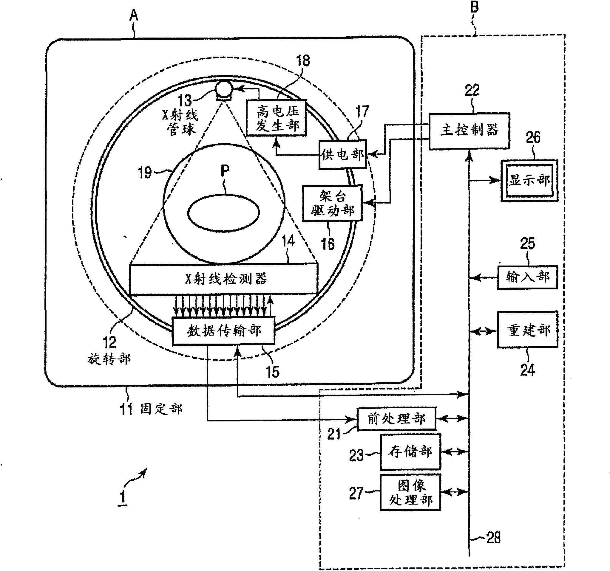
[0040] figure 1 A block diagram showing the overall configuration of the X-ray CT apparatus 1 in the first embodiment. As shown in the figure, the X-ray CT apparatus 1 is constituted by a gantry unit (gantry unit) A and a console unit (console unit) B. As shown in FIG.
[0041] The gantry device A irradiates the subject with X-rays and detects the X-rays transmitted through the subject to obtain projection data (or original data). In addition, the imaging series of the X-ray CT system has a rotation / rotation (ROTATE / ROTATE) type or multiple detection elements in which the X-ray tube and the two-dimensional detector system rotate around the object as a whole. Arranged in a ring, and only the X-ray tube rotates around the subject, there are various types such as the stationary / rotate (STATIONARY / ROTATE) type, but here, the X-ray CT device of the rotating / rotary type that...
no. 2 Embodiment approach
[0088] Next, a second embodiment will be described.
[0089] In this embodiment, instead of providing a heater controller 401 for each DAS substrate 105 to independently control the heaters 205 of each detection pack 102, one heater controller is used to collectively control the heaters 205 of each detection pack 102. , which is different from the first embodiment. The same reference numerals are assigned to the same parts as those in the first embodiment, and description thereof will be omitted.
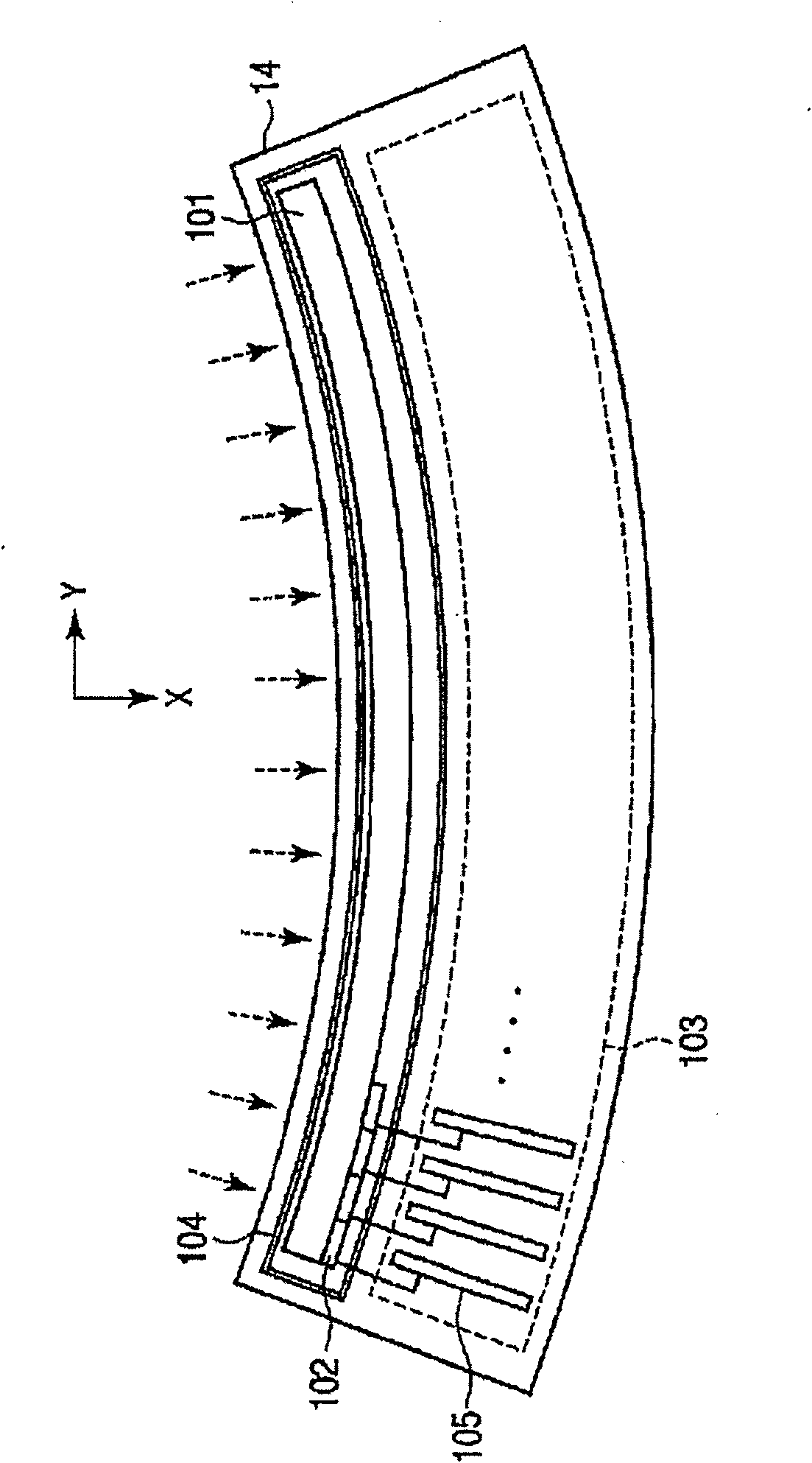
[0090] Figure 8 It is a block diagram showing the circuit etc. of the X-ray detector 14 in this embodiment.
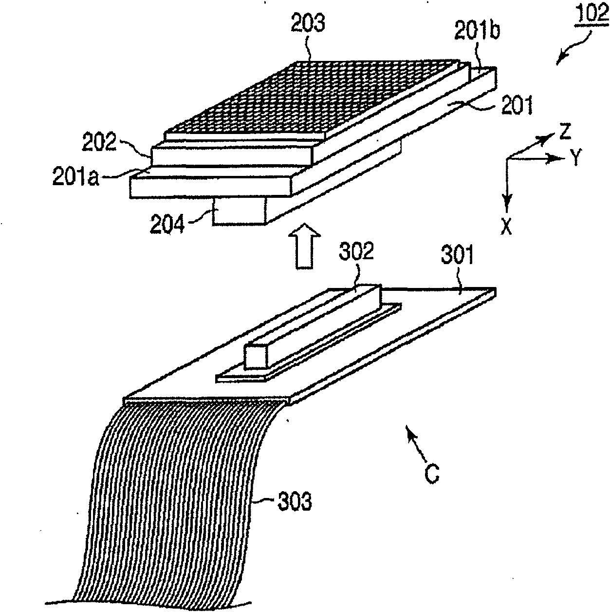
[0091] As shown in the figure, the X-ray detector 14 is provided with a heater controller 501 electrically connected to each DAS substrate 105 . The configurations of the detection pack 102 and the connector board 301 are the same as those of the first embodiment.
[0092] In such a configuration, the heater controller 501 operates with Figure 7 In the control example...
no. 3 Embodiment approach
[0098] Next, a third embodiment will be described.
[0099] This embodiment is different from the second embodiment in that the temperature sensor 206 is not provided to all the detection packs 102 but is provided only to a part of the detection packs 102 . The same symbols are attached to the same places as those in the first and second embodiments, and descriptions thereof are omitted.
[0100] Figure 9 It is a block diagram showing the circuit etc. of the X-ray detector 14 in this embodiment.
[0101] As shown in the figure, a temperature sensor 206 is provided in the detection package 102 located in the center among the three detection packages 102 arranged in a row, and no temperature sensor 206 is provided in the two detection packages 102 adjacent to the detection package 102 . That is, among the K detection packets 102, when the detection packet arranged at one end of the X-ray detector 14 is regarded as the first one and the detection packet arranged at the other e...
PUM
 Abstract
Description
Claims
Application Information