Supercharge Your Innovation With Domain-Expert AI Agents!

Rocking-rolling riveting machine

The technology of riveting machine and riveting head is applied in the field of non-slip pure pendulum roller riveting machine and pendulum roller riveting machine. The effect of good surface quality and low manufacturing cost

Inactive Publication Date: 2012-05-02
武汉长江融达电子有限公司
View PDF9 Cites 5 Cited by
  • Summary
  • Abstract
  • Description
  • Claims
  • Application Information

AI Technical Summary

Problems solved by technology

[0002] The traditional pendulum riveting machine, because its riveting relies on the friction between the riveting head and the rivet to realize the swinging work around the center of the main shaft, there are obvious defects of poor riveting quality, narrow riveting range, and low riveting efficiency; and riveting quality A better radial riveting machine has the disadvantages of complex structure, high manufacturing cost, short life of the whole machine, difficult maintenance, high noise, large vibration, and difficulty in increasing the spindle speed, resulting in low riveting efficiency

Method used


Image

  • Rocking-rolling riveting machine
  • Rocking-rolling riveting machine
  • Rocking-rolling riveting machine

Examples


Embodiment 1

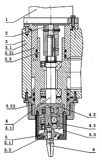
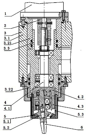
[0022] Example 1: The pendulum mill riveting machine has a motor 1, a coupling 2, a hydraulic cylinder system 3, a spindle system 4, a differential gear train 5 and a riveting head 6; the hydraulic system 3 includes a hydraulic cylinder housing 3.1 and has a shaft hole The piston 3.3, one end of the hydraulic cylinder housing 3.1 is fixed with a hydraulic cylinder upper inner sleeve 3.21, and the other end is fixed with a hydraulic cylinder lower inner sleeve 3.22; the main shaft 4.1 of the main shaft system 4 is installed in the shaft hole of the piston 3.3 through a bearing; One end of the main shaft 4.1 is connected with the transmission shaft of the motor 1 through a coupling 2, and the other end has a main shaft head seat 4.2; a moving gear seat 4.3 is fixed on the end surface of the main shaft head seat 4.2; the differential gear train 5 includes a fixed gear 5.1 and a moving gear Gear 5.2; the moving gear 5.2 is installed in the shaft hole of the moving gear seat 4.3 t...

Embodiment 2

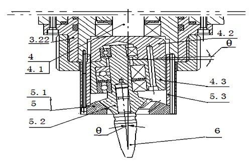
[0023] Example 2: The difference from Example 1 is that the angle between the axis line of the riveting head 6 and the axis line of the main shaft 4.1 is equal to the plane where the main shaft head seat 4.2 and the movable gear seat 4.3 are combined and the plane of the main shaft 4.1. The angle between the vertical line of the axis line, the value of angle θ is 1 to 4 degrees.

Embodiment 3

[0024] Example 3: The difference from Example 1 is that the angle between the axis line of the riveting head 6 and the axis line of the main shaft 4.1 is equal to the plane where the main shaft head seat 4.2 and the movable gear seat 4.3 are combined and the plane of the main shaft 4.1. The angle between the vertical line of the axis line, the value of angle θ is 1 degree.


PUM


Abstract

The invention relates to a rocking-rolling riveting machine, in particular to a nonslip pure rocking-rolling riveting machine, which comprises a motor, a coupler, a hydraulic cylinder system, a spindle system, a differential gear train and a riveting head. The hydraulic cylinder system comprises a hydraulic cylinder shell and a piston with a shaft hole, an upper inner sleeve of a hydraulic cylinder is fixed to one end in the hydraulic cylinder shell, a lower inner sleeve of the hydraulic cylinder is fixed to the other end of the hydraulic cylinder shell, a spindle of the spindle system is mounted in the shaft hole of the piston through a bearing, one end of the spindle is connected with a motor transmission shaft through the coupler, a spindle head seat is arranged at the other end of the spindle, a movable gear seat is fixed onto the end face of the spindle head seat, the differential gear train comprises a fixed gear and a movable gear, the movable gear is mounted in a shaft hole of the movable gear seat through a bearing, the fixed gear is fixed into the lower end of an outer cover connected to the lower end of the piston, and the riveting head is mounted in a shaft hole of the movable gear. The rocking-rolling riveting machine has the advantages of simple structure, low manufacturing cost, no vibration, low noise, long overall service life, easiness in maintenance, fine riveting quality, high riveting efficiency and no slip.

Description

technical field [0001] The invention relates to a pendulum roller riveting machine, in particular to a non-slip pure pendulum mill riveting machine, and belongs to the technical field of riveting equipment. Background technique [0002] The traditional pendulum riveting machine, because its riveting relies on the friction between the riveting head and the rivet to realize the swinging work around the center of the main shaft, there are obvious defects of poor riveting quality, narrow riveting range, and low riveting efficiency; and riveting quality A better radial riveting machine has the disadvantages of complex structure, high manufacturing cost, short life of the whole machine, difficult maintenance, high noise, large vibration, and difficulty in increasing the spindle speed, resulting in low riveting efficiency. Contents of the invention [0003] In order to solve the deficiencies in the prior art, the present invention proposes a simple structure, low manufacturing co...

Claims


Application Information

Patent Timeline
Patent Type & Authority Applications(China)
IPC IPC(8): B21J15/10B21J15/20
CPCB21J15/12
Inventor 刘俊
Owner 武汉长江融达电子有限公司
Features
  • R&D
  • Intellectual Property
  • Life Sciences
  • Materials
  • Tech Scout
  • Unparalleled Data Quality
  • Higher Quality Content
  • 60% Fewer Hallucinations
Learn More